Clementine's Garage
Clementine the Cat
 
Image of flower
Yellow R4
 
Réparateur d'automobiles

Electronic Ignition

Right, I said I would keep you informed, and today I began to install the Aldon electronic kit. So far it has taken me 1 3/4hrs and it won't fit. OK, during that time I had a concerned wife interrupting me to say that water was cascading down the stairs which is almost certainly a seized ballcock but why didn't the overflow do it's job? And we have someone coming to view the house tomorrow. Emergency plumber called out.

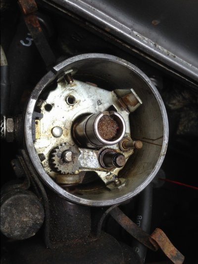
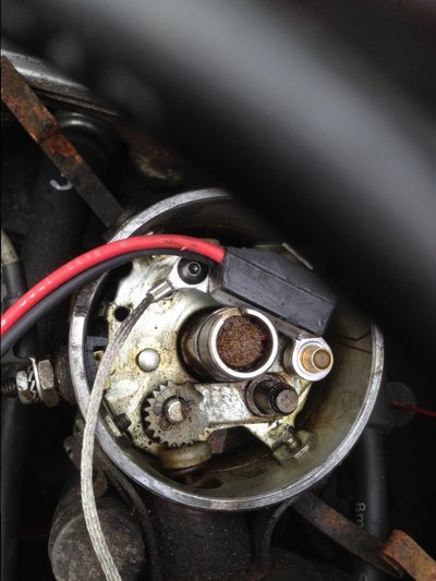
Anyway back to the electronic ignition. The instructions which come with the kit are pretty general and not apply specifically to the EP-141. It doesn't mention that once the points arm is unclipped, the wire at the other end of it requires removing. It doesn't say whether the other side of the points has to be removed - it does. But still the device won't slide down on the brass pin as the plastic points spring guide prevents this. I telephone Paul (Sales Department 01384-572553) and sent him images of the inside of the distributor and he now knows what the problem is but he has to wait until Monday for a colleague, who knows about the Ducellier, to come up with a solution. Clearly the brown plastic bush (at 2 o'clock) has to be removed but surely the entire base plate doesn't need to come out?

Call me cynical (or is it sceptical) but whenever anybody says a particular job is 'easy' or a 'doddle', it never is. So unless someone comes up with a solution, I need to wait until Monday.
 
Two images which show the device.
 
  • IMG_8856.JPG
    IMG_8856.JPG
    111.8 KB · Views: 3
  • IMG_8857.JPG
    IMG_8857.JPG
    107.5 KB · Views: 4
Hello Paul, I've just been out to the garage and here is a photo of the finished article. You keep the part of the points that is held on the base plate by a screw, and the small earth strap is connected to this screw. You must remove the plastic points spring guide, as it's not required. Then you will have clearance to slide on the sleeve to the shaft. Hope this helps, regards Brian. 20170505_163723.jpg
 
Thanks for getting back Brian but five more questions -

1. If the small section of the points is now not needed, why replace it. Surely the screw alone would do?

2. Remove the points spring guide? This is attached to a vertical metal tab. Do I remove both or just the plastic part?

3. You've taken out the central felt pad. Can I assume this also has no purpose?

4. Oh, if the vertical metal tab and guide is removed, points cannot be replaced in the future should the Aldon device ever fail.

5. That long spring clip between the two pegs. Hmm, mine doesn't have one of those.
 
I've made a small mistake here Paul, the remaining half of the points pushes against the module to give the gap between it and the sleeve, must have fitted it in a hurry. Just remove the plastic spring guide, module rests against what is left. The felt pad is missing from my dizzy, retain it. You will need to get that spring clip, or look on eBay for very small c clips. Maybe for now a small cable tie will do the job.
 
Thank you Brian, I feel happier now. Especially as the emergency plumber has sorted out the waterworks
 
Brian

Did I say 'happier'? It's all back together but the car won't start. Some points -

1. Condenser - I have removed this as I presume without points it is not required?

2. Earth tail - I've attached this to the points screw.

3. Gap between device and magnetic disc - I set this at 0.5mm but then realised this would allow the device to move a little. I altered it so that the points presses against the device to it is snug against the vertical tab.

4. Device label - As a last resort I removed the label wondering if it might 'obstruct' the magnetism somehow. I see yours remains in place.

5. Wires - black to negative on the coil, red to positive.

Still won't fire up. I've left a message for you in 'Conversations'.
 
Hello Paul.
Yes, condenser not required.
Yes, braided earth to points screw.
Yes, remaining part of points pushing against module, although mine worked with module flapping about, which was wrong.
It works fine with label left on.
Red to pos, black to neg, not being funny, but I presume you still have original wire from switch connected to coil, pos side.
 
Aah! No, I removed that original wire as there's no longer a terminal for it on the side of the distributor. I'd better look at your image again.

Nope, I can't see it. I'll replace it but where should it now attach to?
 
It's the white wire from the ignition switch that was connected to pos side of coil, and should remain there. The one you have removed is the from the neg terminal on the coil to the distributor, you did right to remove it.
 
Right, err, OK then. Just checked. White wire to + is still in place. Black to -. Red to + also. Everything else is identical to yours. It won't start.
 
IMG_8860.JPG IMG_8859.JPG


I didn't have a long clip as you have but fitted an e-clip on one post. The correct size e-clip won't fit on the other post as it interferes with the magnetic disc thingy. All other wires are as on yours. The funny squashed appearance of the red wire appears to be a manufacturing fault and wasn't through being squashed. Everything else is identical.
 
There is no wire from the ignition to the coil Paul. Looks like only the 2 wires of the Hall sensor are there.
 
Hello Paul, I see no reason why your car shouldn't start. You seem to have everything correctly done.
 
Looking at your second picture, Paul. The wires look somewhat cooked. Or am I seeing things that aren't there.
 
There is no wire from the ignition to the coil Paul. Looks like only the 2 wires of the Hall sensor are there.
Looking at your second picture, Paul. The wires look somewhat cooked. Or am I seeing things that aren't there.

That strange thing on the red wire, which I thought was there when I took it out of the packaging, just might suggest it breaking down. I'll double check in the morning.

(Later) Actually looking back at yesterday's image at 1417hrs, that red wire wasn't like that. It's not right.
 
Lying in bed last night and mulling over things in my head as to what on earth could be wrong. Firstly perhaps I'd managed to squash that red wire and perhaps it was shorting out, then I began to wonder how the electricity got to the HT leads without a rotor arm.

This morning I re-read the Aldon instructions sheet, and No12 said "Replace rotor arm...." Jesus, Of bloody course. Why did my aging eyesight gloss over that crucial point?

Incidentally the wire wasn't cooked nor squashed, so that roughness was just a manufacturing fault with the rubber insulation.

Once I replaced the rotor arm, she fired up, not particularly smoothly, so I let her tick over for a while then took her for a short drive around the block. Well she goes but there's a slight hesitation when depressing the accelerator. Perhaps I need to get my strobe out? Perhaps the ballast resistor also needs to be reconnected? This also is mentioned in their instruction sheet. I'll take her out later and see what she's like on the open road.
 
Oops, ignore my last, I'm mixing up a balance resistor with a condenser.......which of course is no longer required.
 
Oh Paul, that really was a senior moment. Believe me or not, I had thought rota arm? But then I thought no, Paul would have refitted that. Anyway, there you are, I take it your car is running lovely now. Happy motoring. Regards Brian.
 
Last edited:
Back
Top