Clementine's Garage
Clementine the Cat
 
Image of flower
Yellow R4
 
Réparateur d'automobiles

no spark.. changed everything related to the distribution/ignition and still not working!

O.K., we're making progress.... Next questions:
1/ What is the resistance across the coil? To find this, select the maximum resistance setting on your multi-meter (usually 2M ohms) and connect the leads to the two small terminals (the "+" and "-" terminals of the coil) What is the reading and does it remain constant?
2/ Is the bracket supporting the coil tight? This bracket earths the coil's so it should tightly hold the coil in place. If it's loose, tighten it up.

Let's solve this problem!
thanks for the help andre!
i already know the answer to the second one and it’s yes.
i need to check for the first one, but i know it’s not internally grounded (checked for continuity between contacts and body).

here’s what made me think that the short is down the line (under the dash) on that 12v line: taking the 12v cable that connects to the coil, disconnecting it, and using the multimeter to check from that cable end to a good earth it shows continuity. another red flag is that is shows continuity from the battery + even with the key not turned.
plus, i can see some frayed cabling under the dash. maybe it’s rodent damage!
 
Personally I would suggest you remove the distributor complete, along with the coil if its an old one, a bin them both. Next, invest in a good quality coil and a 123 electronic ignition distributor. Forget those crappy points and condensor and enjoy trouble free motoring. I know its not cheap, but once fitted you won't regret it.View attachment 35365
yeah i know.. but our car has a special certification (asi gold plate, if you know what that is) that means it’s got everything oem spec. replacing the distributor would get that removed on the next check that they do.
 
A lot of advice is already given by forum members especially by @André4Renaults

The working of the ignition circuit is very very easy as long as the basic criteria are met such as setting the correct timing and point gap (0,4mm).

Here's the theory of operation as I learned it at elementary school electronics, should also work for a junior automotive student

The battery voltage is much too low for a spark plug to spark. The battery voltage is therefore increased to a value of 10,000-30,000 volts using the coil, which is nothing more than a transformer.

The breaker is opened and closed by a polygonal shaft (in a four-cylinder engine this is square) with rounded corners, the distributor shaft. This is usually driven by the engine's camshaft and therefore rotates synchronously with it, at half the speed of the crankshaft. In the rest position, the stop of the breaker rests against a flat side of the distributor shaft and the circuit from the positive pole of the battery is closed by the primary winding of the coil to the negative pole (which is on the chassis). A magnetic field builds up in the coil through induction.

Ignition takes place at the moment that the breaker opens because one of the corners of the distributor shaft reaches the stop and as a result the arm of the breaker lifts (the contact points are opened). At that moment the magnetic field disappears and that causes a very fast (steep) induction current surge with high voltage that discharges over the spark plug. Between the electrodes of the spark plug this high voltage bridges a small distance through the air and that gives the ignition spark.

The capacitor plays an important role in this. Its task is threefold.

1. it absorbs the induction current surge so that no spark occurs between the contact points of the breaker. Without a capacitor the contact points would burn in very quickly.

2. the capacitor together with the self-induction of the coil (they form a so-called LC circuit) ensures an alternating current in the coil that can therefore function as a transformer: a direct current cannot be transformed.

3. the capacitor ensures the highest possible induction voltage. Charging the capacitor at the moment the contact points are opened happens so quickly (the increase is so steep) that the magnetic field of the coil collapses much faster (approx. twenty times faster) than would be the case without a capacitor. In simple terms: the power stored in the coil does not simply flow to the ground, but the coil is, as it were, sucked empty by the capacitor. This creates a much higher voltage peak on the secondary side of the coil, which ensures that a very bright spark is generated between the electrodes of the spark plug.

The high voltage is led to the center connection of the distributor with a spark plug cable, and the rotor mounted on the distributor shaft (and therefore running synchronously) ensures that the high voltage is led to the correct spark plug.
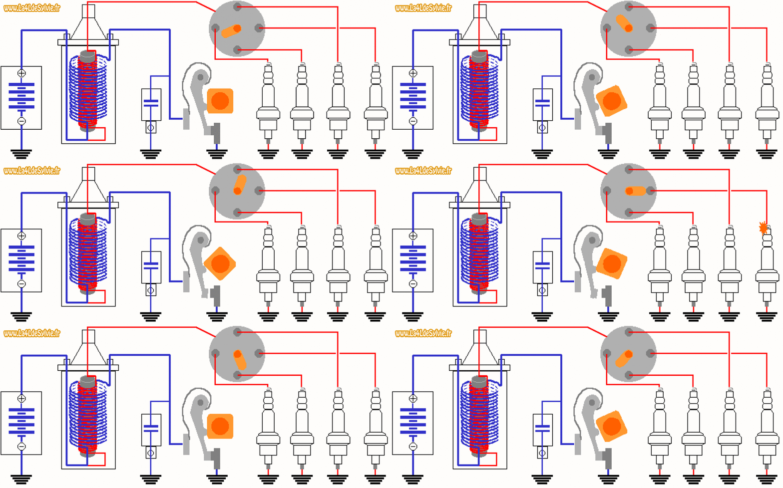
1726583570825.png


animation-allumage.gif
thanks for the explanation! yes, i already knew how all of this worked, but the animations make things a whole lot easier to understand!
 
Just in case of measurement error - continuity measurements will give false readings if the ignition is switched on.
 
Just in case of measurement error - continuity measurements will give false readings if the ignition is switched on.
yep. every measurement was done with ignition off, besides when i checked for the first time for 12v from battery to coil
 
yeah i know.. but our car has a special certification (asi gold plate, if you know what that is) that means it’s got everything oem spec. replacing the distributor would get that removed on the next check that they do.
Is that such a problem Gabriele? We are lucky in the UK, but I didn't realise changing a small part like the dizzy would upset the system in your country.
 
Is that such a problem Gabriele? We are lucky in the UK, but I didn't realise changing a small part like the dizzy would upset the system in your country.
this doesn’t apply to all cars!
however, for a car to be registered on the register (asi, like ours is) it needs to still match original spec and have oem parts;
the gold plate is even more exclusive - it comes with benefits and tax cuts, but requires the car to be pretty much in the same condition it left the factory in. ours underwent some conservative renovations to be able to apply for it.
obviously even if you car is historic but it’s not on the registry you are free to do whatever with it.
this is not our daily driver, so as long as it works (or i can get it working) on the weekends that’s good enough.
 
Now I understand why you want originality, it makes sense I guess. Sorry I can't help with the problem you have, but you have come to the right place with members that have the knowledge, and I'm sure the problem will be resolved.
 
Having had a long think about this I can only suggest bypassing the ignition switch and dashboard wiring by running a wire from the "+" 12 volt terminal on the battery, straight to an in-line fuse and then to the "+" terminal on the coil, using a clip to hold it in place. This would remove any problems you might have within the car's wiring. Then carry out the same checks and see how things are. Try starting the engine and see how it runs and feels.
 
Don't know if you've solved your problem yet. Two things crossed my mind. Firstly are your rotor arm and distributer cap compatible, did you buy them together as a set?

Secondly I had a problem with a set of contact points. They worked perfectly and then after a couple of months I couldn't get a spark. I took the points out again and with my multimeter set on continuity, I touched the leads to each side of the points and got no reading. With continuity there is supposed to be a beeping noise.

Andrew or someone, can you verify that this is the correct way of testing?

It took me a long time to discover the problem and its the last place I looked because the points were new!. When I replaced them (with an old set that I had kept) the problem was sorted.
 
The only definitive way to confirm whether the points are functioning correctly is to remove them from the vehicle, but if this is impractical, one can proceed as follows: disconnect the lead that runs from the distributor to the coil and attach one of the lead from the multi-meter to it. Now attach the other lead from the multi-meter to the car's earth. With the connections made in this manner the points are electrically isolated from the car's battery and the only other component in the circuit is the capacitor. With the plugs removed, making rotating the engine easier, turn the engine and the meter reading should go from '0" when the points are closed, to "1" when they're open.

If the points are removed from the car attach one of the multi-meter leads to the wire from the points and hold the other lead to the body of the points, where the screw would secure them to the distributor body. Wearing gloves (to prevent leakage) now open the points; the reading should be "1", and when they close under spring pressure the reading should be "0" Anything more than "0" suggests the point faces aren't meeting each other properly and/or are dirty. New point sets are sold with a protective coating on the point faces; this needs to be removed before fitting them to the car.

I hope the above is of use.
 
Thanks for the advice Andrew, can you please confirm what setting to use on the multimeter? Is it continuity like I mentioned above or something else?
 
Continuity testing is usually marked by an Omega symbol, the highest setting is normally 2M ohms. To test you're on the right setting, touch the two terminals together and the meter should read "O" and when apart they should read "1", which means when touched there's NO resistance (dead short) and when not touched there's infinite resistance (open circuit)
 
Continuity testing using the 2M or infinite ohm setting uses the multi -meters internal battery, as meters are usually a back of the toolbox tool when doing the initial lead lead test for a full deflection ( infinite resistance to short) its worth holding the leads together for a few seconds to see it stays full on a full deflection (0 ohms), if the reading falls slowly it means the meter has low battery, the longer its left on on this scale the further from the truth the actual reading. Without checking this 1st you can be chasing faults that don’t exist.
 
Back
Top