Clementine's Garage
Clementine the Cat
 
Image of flower
Yellow R4
 
Réparateur d'automobiles

Suspension Bushes

malcolm

& Clementine the Cat
Messages
4,519
Location
Bedford UK
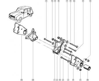
I've bought a set of front suspension bushes that includes the lower arm inner bush. It's metal sleeved inside and out, but there doesn't appear to be access to press out the bush by the outer sleeve. Has anyone replaced this bush?

fr-susp.jpg

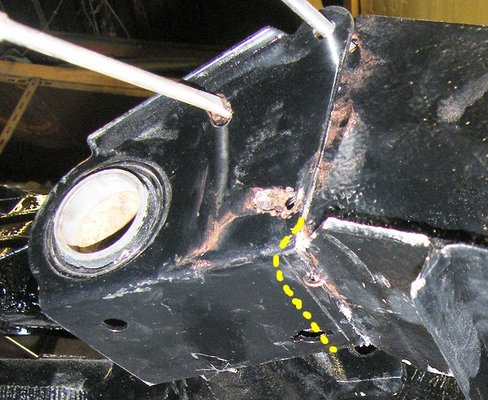
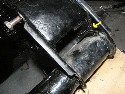
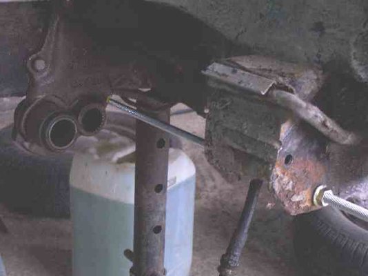
Onto the rear suspension. My manuals are rubbish for later cars (hence this post). Really ought to seek out a factory manual that covers the GTL. Does anyone know what type of bush holds the suspension mounting to the inner mounting (arrowed in the photo)? I have a new outer mounting and I'm tempted to replace the inner mounting while I'm at it (but first more struggling with the torsion bars).

rear-susp.jpg
 
Malcolm, regarding the rear inner mounting, the bush and inner mounting plate are one unit. If you are replacing either the inner or outer mounting they have to be pressed on in exactly the correct position otherwise the body height and suspension will be affected. Trouble is that no Haynes manual gives these measurements or an idea of the jig needed to position these mountings. I would have thought that the official Renault manual would tell you but I have never seen one advertised for the later GTL models. Do you want to replace these mountings because the rubber looks perished?? If so, the perished rubber only goes skin deep so it may be best to leave well alone until you have measurements/details/jig to replace the mountings.

I did actually strip a rear suspension unit and it took lots of heat to remove the torsion bars as they were seized in, but the heat ruined the rubber bushes. I have a feeling that Renault built and designed the rear suspension to last the 'lifetime' of the vehicle!!
 
Hi Malcolm,

Is the section you were talking about ...item number 1 7700627830 £101.46 plus vat....
 
  • renault 4 rear axle.jpg
    renault 4 rear axle.jpg
    13.4 KB · Views: 696
That's annoying. My main reasons for removing the torsion bars were so the arms would fit in the shotblasting cabinet and to make the suspension small enough to fit on the press so I can press on the new outer bush (the old one is rusty). Orientation of the outer bush isn't critical - it just reduces stress on the rubber.

Could use 2 axles - heat one to remove the torsion bars, then use them on another where the torsion bars have been removed by more damaging means.

Maybe the inner bush will be OK (at £100 each I suspect I'll find they are perfectly fine).

I'll play about with a scrap axle and see if I can't break it. :D
 
I've had a better look. The early factory manual is helpful - it suggests both the inner bush at the back and the front lower arm bush are obscured by torsion bar splines, and that if you really want to remove them burn the rubber out and try to cut through the outer part of the bush with a hacksaw blade.

I've also found it's difficult to brace the inner rear suspension mounting against anything to knock out the torsion bars while it's off the car. Not bracing sufficiently will tend to disturb that inner bush. I'll wrap the torsion bars with rubber and blast the rear suspension outside.

That makes pressing the new rear suspension outer bush tricky. I could mount the press on a table for the extra height. But it's not my press and the owner would be very upset if I did this. Also I'd need to make a bolt together base for the press. Has anyone tried hammering them on?

The one thing I didn't find was my 16mm rough road spec front anti-roll bar. In fact my whole collection of anti-roll bars has gone missing. I've no idea how I manage to be this disorganised. Fortunately I have a 17mm bar (possibly) on a R5 Gordini as a backup.
 
What you have decided to do is what I found the nastiest job on any Renault I have worked on. It makes changing the starter motor on a 16TS look easy! :-)

With the front bushes, try using a rod the same diameter as the inner torsion bar splines. even though it will be bearing on the rubber portion of the bush, the bush can push through, I've had a 60/40 success rate with this method. The 40% that don't work, you have to get out the new hacksaw blade and cut a slot in the outer section of the bush, bend up the edge, then twist and hope the bent bit draws the rest of the section around and out and doesn't just snap off! It is all about time and patience. The two essential items necessary in any old Renault set of special tools!

The inner rear bush is similar to the front, but on the early cars you have to remove the bracket first to get to the outer section of the bush pressed into the arm. And the outer bush section has to be hacksawed (or I guess there may now be a Dremel cutter tool) with a groove in order to lift up an edge and extract the bush portion. If the bush is secure, and doesn't look cracked or perished, I wouldn't bother with replacing it. On my early car I used the Spanish manufacture Neumarsa inner and outer bushes, 12 odd years and 25K miles and they still seem OK.

As for orienting the bushes, make sure they are not fitted in a stressed position at normal ride height. I went for a dummy fitting on the chassis to set them up, and you can use paint, chalk, or probably blood, to mark the relative positions on both items where the bush needs to be placed so it suffers least stress at a normal ride height. Also try not to place any lateral load on the rubber portion of the bush itself when pressing it back into place.

As for hammering the outer bush in place, probably not recommended, as the inner portion of the bush will likely distort on being hit, making it really difficult to get the bush into place.
 
These bushes are meant to be destroyed when removing them.There is on other way.
Orientation on reas ones-both outer and inner- IS critical. You will have problems with aligning the holes when fitting the arm to the chassis if you don't care. The factory manual describes clearly this procedure (the RTA too). But you don't need such sophisticated equipment as describes, a flat table and some wooden blocks to hold the arm at the desired position are OK.
I have always driven these bushes home by hammer, having oiled their bores beforehand, and had no problem.
The torsion bars will be hard to release from the splines...try lots of penetrating oil for 2-3 days, and when removing them, hit them from both sides, and also try to move them sideways, your goal is to break the corrosion. That said, I have met torsion bars that had been removed "as in the manual" with the suspension on the car!
 
I had a practice on some spare suspension. It's possible to remove the front lower wishbone bush by pressing out the center, cleaning the rubber off, then tack welding a nut inside the outer sleeve and using that to push out the sleeve.

tack-nut.jpg

I had been planning to use rough road suspension from my '83 Spanish TL, but look what I found. The upper wishbone bush housing is formed from a tube with a split, and the split is orientated towards the wishbone on the other ones I looked at. This one is orientated away from the wishbone and a crack has started.

crack.jpg

I've decided to use the GTL suspension from the dented yellow car previously owned by a mad hippy woman. It is in good condition. The original bushes look fine, so I'm planning to leave them in place rather than replace them with my new bushes. Aftermarket rubber often doesn't last so long as original rubber, and I'm not sure where my bushes were made.
 
It's possible to remove the front lower wishbone bush by pressing out the center, cleaning the rubber off, then tack welding a nut inside the outer sleeve and using that to push out the sleeve.

Nice! An easy simple solution!
 
I was very careful to align the outer rear suspension mounts using a steel rule and a square to reference the hub position, and I pressed them in just the right amount (apart from the one I pressed in 2mm too far). Thanks Angel - they did hammer on with a lump hammer and a steel plate to spread the load.

But the rear suspension just wouldn't go on. It's always trickier on a bare chassis as there's no weight to push against, but this seemed worse. I checked all my measurements again and everything seemed fine. Paint removed, copper grease applied for lubrication, and finally after several hours the suspension was mounted on the car. And then I found the problem.

The replacement outer mountings are '60s style and my chassis repair is '80s style. '80s style rear outer mounts have a cutout (yellow line in the photo) to allow the mounting to twist to the limit of the adjustment slots. After all that the rear suspension will need to come off the car again for modification. :shock:
 
  • rear-outer-mount.jpg
    rear-outer-mount.jpg
    122 KB · Views: 651
Ouch these things do like to try us don't they!!

Its always the adapting of things that takes the time.

My friend has just put a new engine into his Bay window bus and wanted to fit an oil cooler at the same time, it took him longer to mount and pipe the cooler than it did to replace the engine!

My VW bus is even worse a I run a Peugeot Diesel engine in the back, everything I do takes time to plan and build and then check if you don't then something always back fires.
 
Try us they do. Dropped the rear suspension to modify the outer mounts, and that did make it easier to fit the second time. But guess what - the weld on the outer mount fouled the sides of the chassis member. They were only 1mm too long but it meant dropping the suspension once again.

Finally it's on - third time lucky!
 
  • rear-susp-foul.jpg
    rear-susp-foul.jpg
    95.2 KB · Views: 142
Just remembered something else.While the factory manual gives measurements for correct alignment for both the inner and outer mountings on early cars, there are no measurements for post '77 cars with the cast inner mountings (and the method described for the earlier pressed steel mounting cannot be utilized).
So my solution was the following: I bolted the new inner mounting on its position on the chassis, then passed an M8 rod through one of the outer mounting holes, and tightened it. Then I marked the position where it met the inner mounting.
I pressed the new outer mounting on the arm first, and by screwing the rod on the same mounting hole as used on the chassis, and aligning it with the paint mark, I was able to determine the correct inner mounting position in relationship to the outer.
The holes aligned perfectly when putting the assembled arm back.
 
  • susp4l.jpg
    susp4l.jpg
    36.2 KB · Views: 136
That's a sensible method. I measured my chassis and measured a spare rear suspension. I suspect I've knocked both outer mounts in too far by maybe 2mm. (Oddly enough the spare factory assembled axle bushes look a bit distorted too). Once I have some weight on the chassis I'll adjust the tracking and see if it looks OK. Otherwise remove once again, cut the mounts off and fit another new set.

If I were do the outer mountings again I would knock them in 4mm short of the position. It would be much easier to tap them during assembly than to pull them outwards.
 
Back
Top