Clementine's Garage
Clementine the Cat
 
Image of flower
Yellow R4
 
Réparateur d'automobiles

How to: Set front ride heights

angel

Enthusiast
Messages
2,444
Location
Athens, Greece
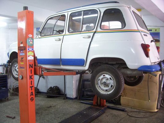
The Jogging will have to make it through rough terrain this week, loaded, and was running a little low up front, so the ride height had to be reset.

I decided to set them according to the standard setting (H3=41mm). Normally it should be 5mm lower (H3=46mm) as it's fitted with tripod inner driveshaft joints., but as it is going to be loaded, the suspension would sag anyway, so inner joints will still be in a safe working angle.

After measuring it on a level floor, I noted the following:

LH wheel: RH wheel
H1=260 mm H1=260mm
H2=203 mm H2=207mm
H3=57mm H3=53mm

So it needed correcting by 16mm at the left wheel, and 12mm at the right wheel.
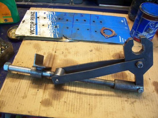
I decided to do a photo how-to of this procedure...

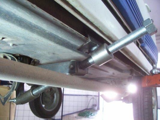
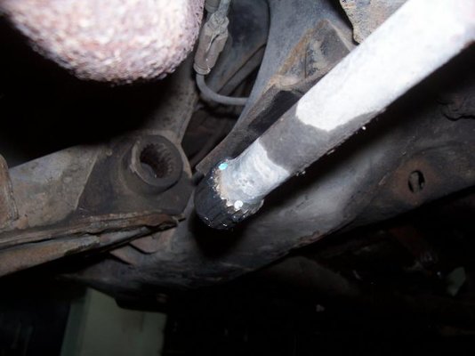
First of all, car needs to be raised so that the front wheels are off the ground. I have the luxury of a two-post lift, but raising it on axle stands works equally well.

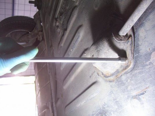
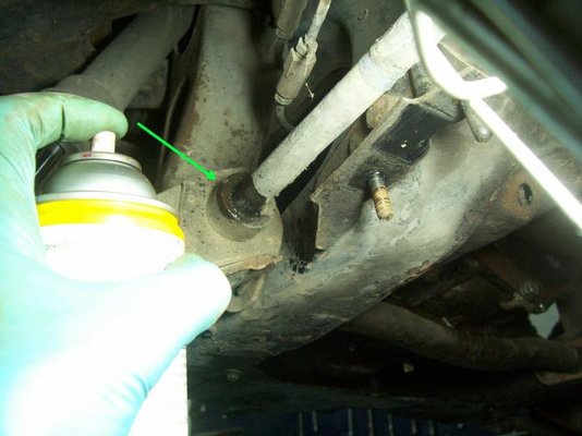
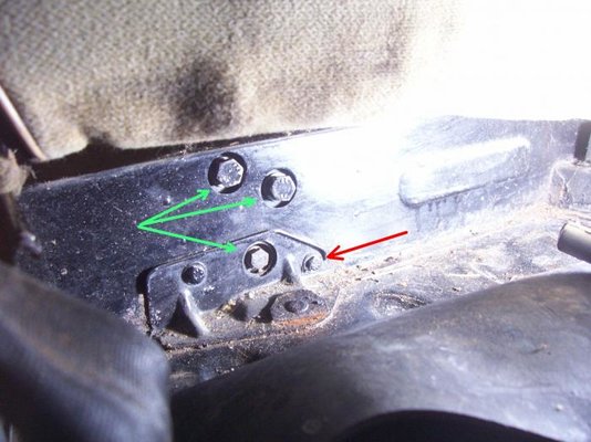
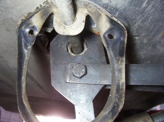
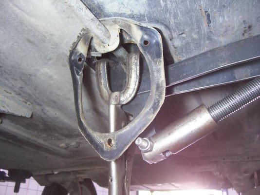
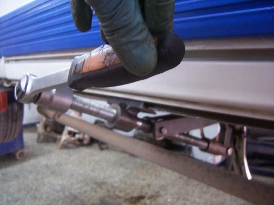
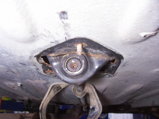
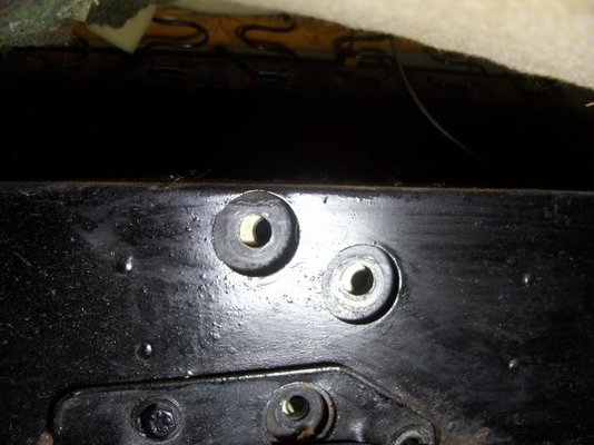
The first step is to remove the torsion bar anchor lever cover (10mm spanner). The rear nut will need some penetrating fluid.
 
  • 100_6753.jpg
    100_6753.jpg
    54.4 KB · Views: 226
  • 100_6754.jpg
    100_6754.jpg
    39.9 KB · Views: 228
If you don't remember when was the time you last removed the torsion bars (which is more than often the case!) soak their splines at the lower wishbones with penetrating oil. It's a good idea to do this on the anchor lever end, too, but it will always be cleaner and easier to remove.

Wire brush the torsion bar boss on the wishbone. Now you can see the punch mark (arrow) that will be used for marking the torsion bar position.
 
  • 100_6755.jpg
    100_6755.jpg
    42.5 KB · Views: 234
Slide the front seat fully forwards (the left one, as we are working on this side), and loosen the three bolts that fix the torsion bar anchor lever (green arrows-17mm and 13mm spanners). 1-2 turns is enough, don't loosen them more at this time.
The red-arrowed bolt (10mm socket) also needs to be loosened for about 10 mm or removed completely for reasons that will be explained later.
 
  • 100_6757.jpg
    100_6757.jpg
    55 KB · Views: 231
Now we need to take tension off the torsion bar. I use my own version of Renault SUS-28 tool, as I'm working alone. If an assistant is available, the levers and screw can be substituted for a long steel tube, but a spanner that safely fits around the torsion bar octagon is still necessary.

Make sure it fits correctly on the anchor lever. As the octagon is tapered, the tool can slip off when under load. Renault noticed their mistake, and advised the fitting of a locally made hold tool. I have found that welding lock grip pliers work equally well.
 
  • 100_6756.jpg
    100_6756.jpg
    57.2 KB · Views: 247
  • 100_6760.jpg
    100_6760.jpg
    49.3 KB · Views: 237
  • 100_6761.jpg
    100_6761.jpg
    51.8 KB · Views: 236
If you are using the SUS-28 on the left hand side, the exhaust pipe gets in the way. It does not need to be removed. Just release it from its rubber mounts and let it hang down after loosening the clamp just before the inner wing hole.

On the Jogging with the rear mounted silencer, it needed to be supported with a strap.
 
  • 100_6758.jpg
    100_6758.jpg
    45.9 KB · Views: 222
  • 100_6759.jpg
    100_6759.jpg
    44.6 KB · Views: 216
If you have the mechanically activated SUS-28 tool, tighten the screw to take tension off the anchor lever fixing bolts. You will notice a point where the screw cannot be tightened more; back it off one half of a turn and all three fixing bolts should now be free to remove by hand.

If you have the voice activated tool (assistant) tell him/her to push the tool (counterclockwise for the left hand bar when viewing from the rear) while you check the three fixing bolts. At the point where they can be turned easily, tell him/her to hold there and remove the bolts.

The anchor lever should now be released slowly (either from the assistant or by loosening the SUS-28 screw). The torsion bar should now not be under tension.

If you did not loosen the small M6 screw mentioned earlier, chances are that the anchor lever stops against it, and tension cannot be taken off completely.
 
  • 100_6762.jpg
    100_6762.jpg
    36.4 KB · Views: 219
  • 100_6763.jpg
    100_6763.jpg
    40.9 KB · Views: 220
Before taking the torsion bar off, marks should be made to its ends. They should be at a spline tooth so that counting will be easy later. Start with the anchor lever end, as the wishbone end splines are not yet visible.
 
  • 100_6764.jpg
    100_6764.jpg
    44.7 KB · Views: 313
The torsion bar anchor lever can now be slid forwards until it's free from the torsion bar splines. A large screwdriver should be sufficient for this.

Now it's the hard part of the job...Assuming that on the earlier steps you did not forget to spray and spray again penetrating oil in the wishbone torsion bar boss, it should not be too hard. The best way is to knock the wishbone with a hammer at the point shown in the photo, while pulling the torsion bar rearwards with your other hand (or the assistant-if he or she is not too fatigued or bored...). At the same time correct the torsion bar position at the rear, so it is free to pass through the hole on the anchor lever sheet metal boss.

After some knocking you will notice the torsion bar emerging from its boss. Stop as soon as you see its splines, clean it carefully and mark the tooth opposite the wishbone punch mark. Continue the pulling-while-knocking-on-the-wishbone operation, and you will soon have the torsion bar free in your hands.
 
  • 100_6765.jpg
    100_6765.jpg
    42.1 KB · Views: 224
Although the torsion bar need not be removed to set the ride height, it's now a great chance to do so and wire brush its splines so they are clean. Be very careful not to lose the marks previously made. On refitting it, pay extra care in positioning the sealing rubber for the anchor lever the correct way up. It's very frustrating re-tensioning the bar and putting all in place, only to discover that the cover does not fit and the torsion bar has to be removed again!

From the measurements taken, determine the number of teeth the torsion bar needs to be turned. On my case I needed to correct ride height by 16mm. Dividing it by 3, we get 5,333 teeth. Although 5 teeth would be right, I decided to go to 6 teeth, as it's the driver's side which is allowed (and in fact is desirable) to be a little higher.
According to the workshop manual, the left hand bar should be rotated clockwise (as viewed form the rear) to raise the car. So I made a second mark (white), 6 teeth counterclockwise from the original position (blue mark).

Smear the wishbone end splines with graphite grease. This is very important in order to remove easily the bar some years later. Fit it on the wishbone so that the white marked tooth coincides with the wishbone punch mark. Light knocking brom behind may be needed.
 
  • 100_6767.jpg
    100_6767.jpg
    33.2 KB · Views: 211
Now it's time to position the anchor lever in a way that the two marks previously made are positioned 6 teeth apart. The torsion bar mark should have been moved clockwise in relation to the anchor lever mark.

Again the splines must be smeared with graphite grease. Make sure all parts are positioned correctly. The torsion bar should not protrude behind the anchor lever; if yes, it needs some more tapping from behind to move further in the wishbone boss.
 
  • 100_6768.jpg
    100_6768.jpg
    38.8 KB · Views: 215
The torsion bar should now be re-tensioned. Fit the special tool on the anchor lever and tighten the bolt (or tell the assistant to push it, if you are lucky enough and he/she has not gone away while you were busy counting spline teeth).

Watching through the chassis holes you should stop tensioning when the three threaded holes are centered over the chassis holes. Now all three bolts should go in easily. Screw them up and torque them: lower one (M8) to 30Nm, the two higher (M10) to 80Nm as stated in the manual.

The tension on the special tool can now be released, the cover fitted and the car lowered on its wheels. Don't forget the exhaust if it had been removed.

The ride height should be measured again. I thought some meters back and forth and a couple of lock-to-lock steering wheel turns would be enough to settle the suspension. I took again measurements and found the ride heights to be 16mm higher than expected. But after driving the car for less than a kilometer and hitting some bumps, I returned to the workshop and measured ride heights again. Surprise! they changed to the calculated figures. (LH H1=221mm, RH H1= 219mm).

We are now ready for off-roading!

I promise a similar how-to on rear torsion bar removing/setting, when I have the chance.
 
  • 100_6769.jpg
    100_6769.jpg
    47.6 KB · Views: 121
Angel, thanks for this amazing guide! I think the rest of us will be a little less afraid of our torsion bars after this.
Do you mind if I take your text and photos and use them to make a wiki page?
 
Thank you for that angel, an excellent master-class. Looking forward now to part two, the dreaded rear suspension. Easier to adjust I believe on earlier cars, but a bit of a pig on the later models I'm told.
 
Angel, thanks for this amazing guide! I think the rest of us will be a little less afraid of our torsion bars after this.
Do you mind if I take your text and photos and use them to make a wiki page?

No problem at all!
 
Although the torsion bar need not be removed to set the ride height, it's now a great chance to do so and wire brush its splines so they are clean. Be very careful not to lose the marks previously made. On refitting it, pay extra care in positioning the sealing rubber for the anchor lever the correct way up. It's very frustrating re-tensioning the bar and putting all in place, only to discover that the cover does not fit and the torsion bar has to be removed again!

From the measurements taken, determine the number of teeth the torsion bar needs to be turned. On my case I needed to correct ride height by 16mm. Dividing it by 3, we get 5,333 teeth. Although 5 teeth would be right, I decided to go to 6 teeth, as it's the driver's side which is allowed (and in fact is desirable) to be a little higher.
According to the workshop manual, the left hand bar should be rotated clockwise (as viewed form the rear) to raise the car. So I made a second mark (white), 6 teeth counterclockwise from the original position (blue mark).

Smear the wishbone end splines with graphite grease. This is very important in order to remove easily the bar some years later. Fit it on the wishbone so that the white marked tooth coincides with the wishbone punch mark. Light knocking brom behind may be needed.

Hi Angel, a very interesting thread.May i please ask (sorry if its a dumb question) why you divided the 16mm you wanted increased by 3.
Thanks
 
Sorry I was not clear when writing this guide back then. Turning the torsion bar one tooth at both ends raises or lowers ride height by 3mm. This applies to later cars without adjuster cams.
 
Back
Top