Clementine's Garage
Clementine the Cat
 
Image of flower
Yellow R4
 
Réparateur d'automobiles

Intermittant Indicators

daviddb

Enthusiast
Messages
86
Good evening all,

Car is an Oct 77 R4TL , lhd, (type 1126 with 839 engine) and I'm in the early stages of trying to trace why my indicators are becoming worryingly unreliable. Funny thing is the hazards do work with impressive relaibility and vigour. I only have the haynes manual for cars to '79 but which irritatingly doesn't seem to have a wiring diagram for my model, or, perhaps any model with hazards.

Is there, as there is on our Ami 8, a seperate ally 'ticker' canister for the hazards and a second one for the actual indicators? I can see the one that ticks for the hazards in the side of the heater bulkhead to the right of the steering wheel ( 3 pin) but if there is a second unit it's not obvious. I don't suppose anyone has an electrical schematic of how the system should work on a 77 car?

I'm thinking aloud that as the hazard switch must be wired positive ON all the time (hazards working with ignition off) that I may have a problem with either the power (or earth) of the indicator switch itself , or if there is a second canister that may be faulty.

Curiously on the Ami the flasher canister for the hazards is rated for a higher current than that for the indicators whilst the canister I can see on the Quatrelle is rated lower even though it's the one that ticks when the hazards are on.

yours a tad confused and rather damp in the Pyrennees

david
 
Well now but intermittant faults are a tad frustrating to nail down are they not. Big thanks to jjad of this parish for comming up trumps with the relevant wiring diagram. Sadly I've not been able to put a full shift today as the house roof has started to leak and a tempest's worth of rain is on it's way.

In answering my initial question there is, unlike Mr Citroen's small cars of the era, just a single ally ticker can for the whole system but it is a heavy duty one, a Carter gold ( no less) in colour and marked both '0731' and Ref192. Rated for up to six 21w bulbs. Three terminals marked + for positive, R for I know not what and C for , prolly, clignotants. For the greater good I need to get clear in my mind a schematic of how this works - the twin can set up is pretty straight forward.

So switching on the ignition this afternoon and the indicators work. Bit of a hurrah but not yet hosannas. Indicators off and hazards work with ignition on and with it off. Switch ignition back on and indicators no longer work. So smite me down with a torsion bar.... Operate hazard switch rinse and repeat and no joy. Stop for thoughts and a zen moment, and.... ignition on and the indicators work. Pffttt!!

I'm a bit busy marking trees for felling tomorrow but plainly I need to clean and verify the itegrity of the hazard switch, the indicator stalk and the various joints.

More as it happens in the absence of other advice....

regards

david ( still damper than a damp thing in the Pyrenees)
 
Is the fusebox the same on a '77 car as a later one. I had intermittently none working indicators a few years back and it turned out that it was just the fuse that was slightly loose in its holder.
 
Hi Davd
Usually, indicator problems are just the result of dirty connections.
Have you done the following?
Remove the bulbs and clean the contact points inside the holder.
Check the earth on the front of both inner wings
Remove and clean all the wire connectors at the back of the headlights and indicators
Also remove and clean the relevant fuse and its contact points. This happened to me 2 weeks ago

(and apparently to Lobster as well, its not the first time that we've put up a post at exactly the same time:):)

Good luck
 
On cars with factory fitted hazard indicators, the "heart" of the system is the hazard indicator switch itself. It has the task of switching +12V source to the flasher unit from "key switched 12V" when hazards are off, to "permanent 12V" when you switch hazards on.
If you look at the back of the switch there are 7 contacts split in 2 groups. The 3 pin group is what does this changeover. One pin goes to the flasher unit, another has permanent +12V, the other has switched +12V. First of all ensure that you have solid 12V supply to both terminals, if not, check and clean the corresponding fuses. If all is OK, remove the switch and bridge the "switched 12V" and "to flasher unit" terminals on the multi-plug; with ignition on you should have working indicators. If OK, suspect the hazard warning switch, if they are still working erratically, the flasher unit itself is the culprit. Do not rely on a continuity test of the switch, they usually seem to work perfectly under no load conditions.
 
Reading angel’s post explains why there are so many secondhand hazard switches currentley up for sale on the Spanish sale sites, all of them asking more than this link:-
https://piezasautosclasicos.com/ren...-se-al-de-emergencia-renault-4-5-14-y-18.html
If you put link through google translate whole site will be in english ( if req.), deliver to my door in 24 hrs, pyrenees would be same shipping, more or less, which wasn’t to bad to me...
 
Well excellent help from you all and much appreciated. I've just come up for lunch from the garage having spent the morning dismantling and cleaning the Hazards switch having been encouraged by mojobaby's post 'Failed my roadworthy' back in july '14. And Lo! It now all works exactly as it should, so the afternoon woll be spent cleaning up other connectors and earth points as suggested above.

The switch's inner parts, of brass and nylon, are a thing of great beauty but I have to say I just can't get my head round doing a simplified schematic of the hazards and indicators wiring. The dastard electrickery is not my strong point. The switch was most grubby and greasy inside . I confess not to had done anything to access the indicator switch itself for a clean as getting the dash board fascia off seems to be a tad more involved than I'd hoped.

Incidently my own stupidity caused my initial dismay at not finding the right wiring diagram in my deition of Haynes. I've made a mental note to checjk the supplement chapter in future for there it is. Chuh! It's probably old news to you guys but I found a free ( in both senses of the word, virus and monetry) downloadble pdf of the Revue Technique R4 books, all three of them, at www.reseaudesbde.com/revue-technique/

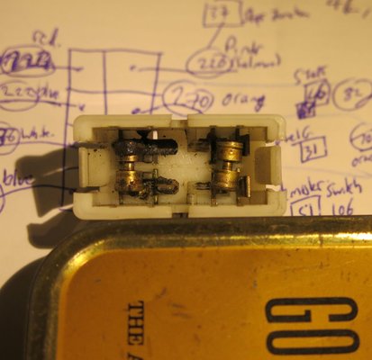
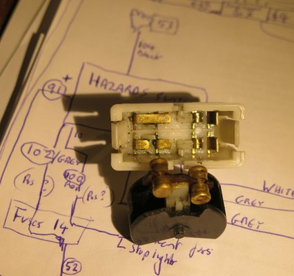
Below are the inner workings of the switch before and after the application of Mr Maplins switch cleaning jollop.
IMG_9116.jpg

IMG_9124.jpg
Next glimmer on the horizon, I see 123 electronic ignition is now available for the Billancourt engine......more as it happens and thanks again all; for the support.

Regards as always

David (unseasonably warm in the Pyrenees)
 
If it helps when connecting the indicator and hazard circuitry, think of it in this way: the power to the indicators (live when the ignition is on) is routed through the hazard switch and this is interrupted (broken) when the hazard circuit is switched on. The hazard switch has a separate power supply (permanently live) and this is used to power the indicators when the switch is activated. In addition, the hazard switch also has separate feeds to both there left and right side lights which are disconnected when the hazard switch is off (otherwise all the indicators would flash when either side were switched on!) and is only connected when the hazard switch is ON. To sum up, when the hazard switch is activated the normal power supply to the flasher unit is disconnected and an alternative supply runs to the flasher unit. The intermittent (flashing) feed is then sent to ALL the indicators. That's why hazard switches have so many terminals!

Hope this helps!
 
That does help Andrew, I had to go into a darkened room to think about it..... But I think that now I have it. And my indicators work!

David (bright sunshine in the Pyrenees but a nip of autumn in the air)
 
Back
Top