Clementine's Garage
Clementine the Cat
 
Image of flower
Yellow R4
 
Réparateur d'automobiles

look what I found

on numerous occasions I tried screwing in bolts to force out the bush but it wouldn't budge.

I went to 2 large Renault garages with the engine and they were both very unhelpful. They suggested screwing in a bolt and hooking it up to a "Reverse" hammer. They couldn't actually tell me what the correct method was according to their workshop manual. When the engine was designed, there was surely a tool designed at the same time to remove the bushing in order to remove the cam.

This afternoon, in desperation, I went to a small garage close by and showed them the engine. They tried the "reverse hammer" trick, which didn't work.
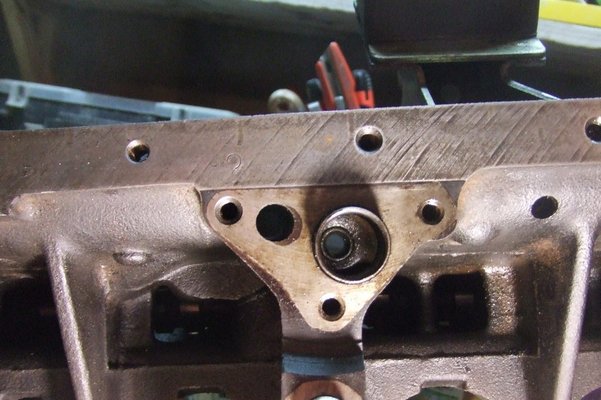
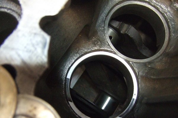
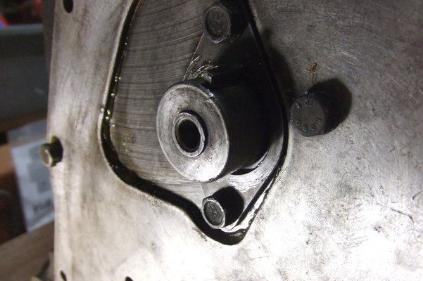
He put the extension bar from his socket set into the oil pump aperture and gently tapped the gear from the bottom. The gear in turn pushed out the bushing above it.

Although it took 15 minutes, there was no charge. Just happy to help me, he said.

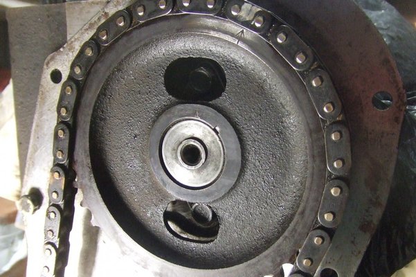
So here are the photos of the bushing halfway out and a view from underneath showing the oil pump aperture and the bottom of the gearDSCF6534.JPG
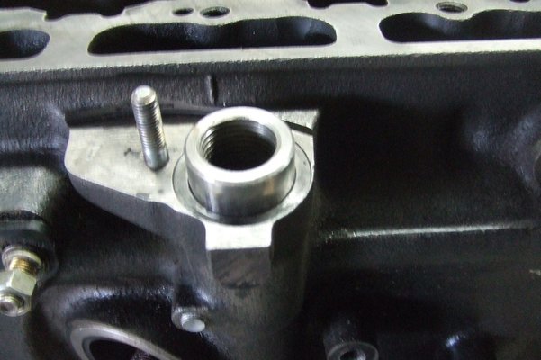
DSCF6539.JPG
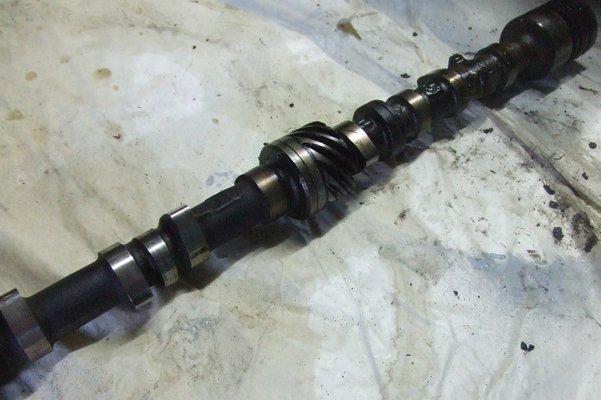
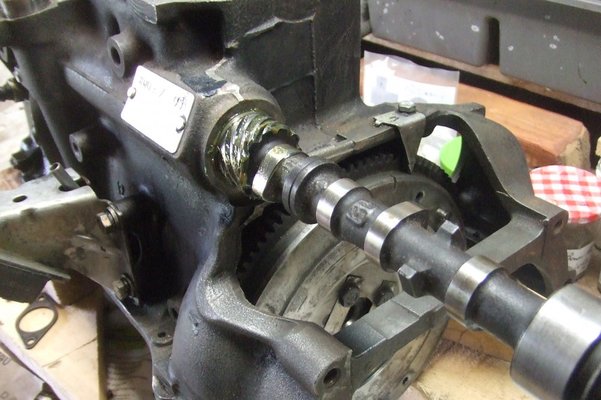
and also one of my camshaft
DSCF6536.JPG
 
That's just too easy. Great idea, thanks for sharing.

Great, i had this same problem two years ago.I also tried to get it out with a reverse hammer(lend by a local motor shop)but no use.i do not recall anymore how i got it out finally.
Decribed method seems very logic to me.
Just don't loose the gear pin for distributor, those are very rare an sold nowhere.I wonder what is the rigth way to set that pin in(how on earth you will know tha rigth angle for your inginition before putting it in(can't put it in with 180degree error, wont go in.??
Another matter what i wonder is the thread in sleeve, it is not for connecting the distributor because it do not have any thread in it.So, obviously it it designed for puller.I could not find any rigth size(dm) puller bolt anywhere(not even from that motor shop), they said that such tools are not anymore used in new motors so it it museum stuff.
 
The workshop manual gives precise instructions for putting the gear pin back in.
And the threads are there simply for the right tool to pull it out - nobody has the tool any more. The manual describes how to use this tool for all the good that does us now.
 
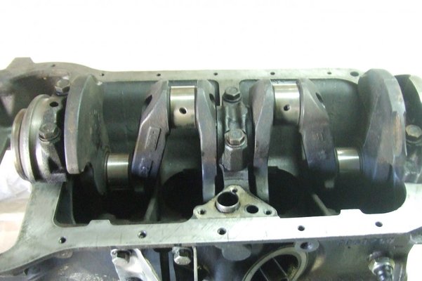
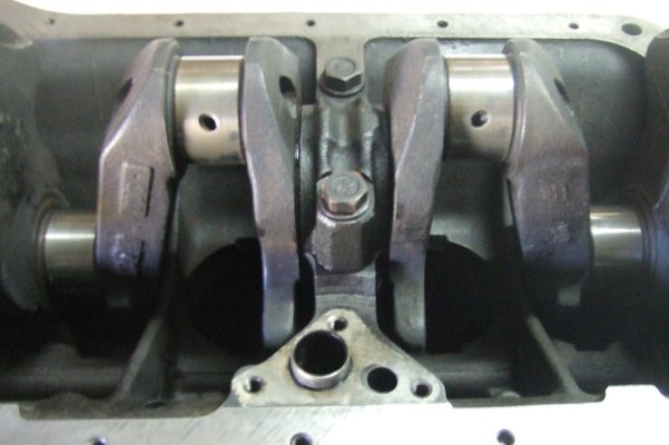
The first step in putting my engine back together. In all the Youtube videos that I've watched, the bearings and journals are first lubricated with a Lubrication Gel, but I couldn't find it at any of the auto shops, so I just used engine oil 20W50.

i then got to use my new torque wrench for the first time to tighten the bearing bolts

DSCF6544.JPG
DSCF6546.JPG
 
Thanks Pepper....as I've only torqued the bearing bolts to 15lbs/foot (to hold them in place) and they eventually have to be torqued to 45lbs/foot, I might remove them again and put grease in instead, as you suggest.

Quite honestly, I was happy to use the oil, as it's the first time I'm doing this job, and my thoughts were that either the lubrication gel or grease might block the oil ways in the bearings and prevent oil getting through. I don't know if that can happen.
 
Oil isn't thick enough to stay in place for the long time it takes for the enine to be rebuilt. Using a small amount of grease and stp, means it stays in place, grease is oil in a soap type solution after all. We used to pack the oil pumps with vaseline when rebuilding so the engine had good oil pressure when first started too.
 
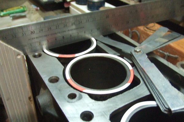
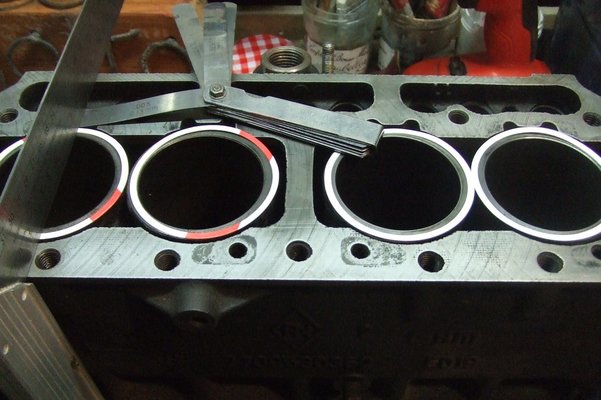
Today I started measuring my liner protrusion to see which size seals to use. Please note that the seals are placed on top of the liners for measurement purposes only. In reality they should be placed underneath the liners

In the gasket set that I bought from Franzose, there are 3 different thickness paper seals, marked with red, black and plain white

The protrusion spec is between 0,04mm and 0,12mm or 0,002 inch and 0,005 inch

It seems ridiculous that these very fine paper seals are all that prevents oil and water mixing together

DSCF6548.JPG DSCF6549.JPG
 
Last edited:
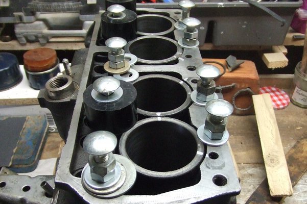
Some photos of the liner seals in place and showing my improvised liner retainers
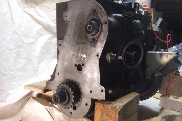
DSCF6563.JPG

You can see the white paint marks on top of the liners that I made to ensure that the liners were inserted in the correct position. The engine block has been placed on 3 inch wooden blocks to protect the crankshaftDSCF6564.JPG
 
Nice job !!!
 
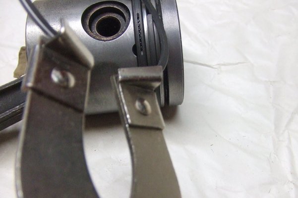
One of the most useful tools that I've bought, is the one that opens the rings so that they can be inserted into the grooves on the piston.
I know that it's possible to put the rings on without the tool, but it's very stressful! I practised a bit with the old rings, but when you realize that a set of rings for one piston is over 20Euros, it's just not worth taking the risk.

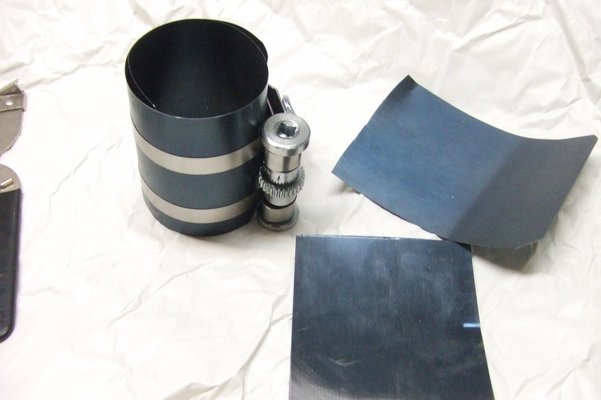
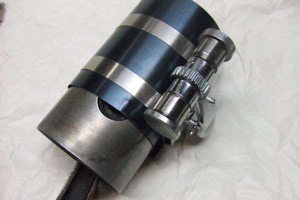
The tool that I bought to squeeze the rings before the piston is inserted into the liner is not so easy to use. Firstly, I had to cut a lot of the metal sheeting off; it was just too long. The shape was more oval than round. It's probably meant for pistons twice the size of mine.
After I cut about 10cm off the end, I had a more round shape, but it was still difficult to hold the piston with one hand and tighten the tool with the other.
Managed to get 2 pistons in yesterday and will do the other 2 tomorrow.
DSCF6565.JPG
DSCF6566.JPG
DSCF6567.JPG
 
After my disastrous attempt at tightening the connecting rod bolts and destroying them with my torque wrench, a complete new set of bolts was bought and this time I was more careful with the wrench settings.
Here is the story of the bolts:-
http://www.renault4.co.uk/forum/threads/connecting-rod-bolts.7174/

Next came the cam shaft, well greased on the centre gear and all the lugs
DSCF6575.JPG

There is a hole on the timing chain side, in the middle, which has a fine mesh. This is the oil feed to the timing chain tensioner. I cleaned it out with carb cleaner and compressed air.

DSCF6576.JPG
 
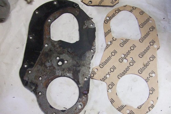
Sometimes it's best to leave the cleaning of some parts til the last moment. That way you can tell exactly where the gaskets are supposed to be positioned. My complete gasket set came with 3 extra timing side gaskets which confused me a little. They're obviously meant for a different engine

DSCF6578.JPG

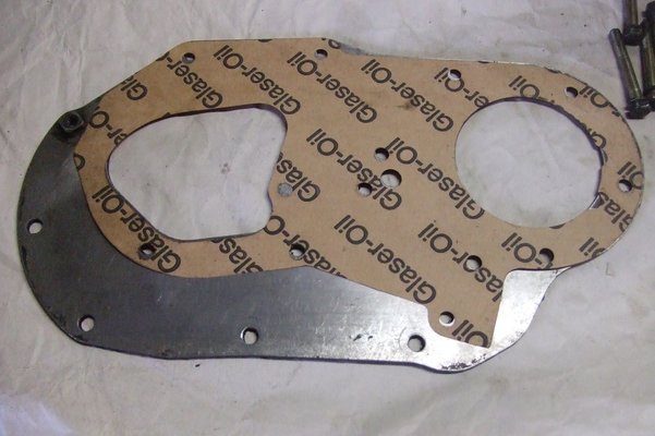
The plate was cleaned up and the gasket had multi purpose grease applied thinly to both sides (Harbourseal's advice) and then assembled.

DSCF6581.JPG
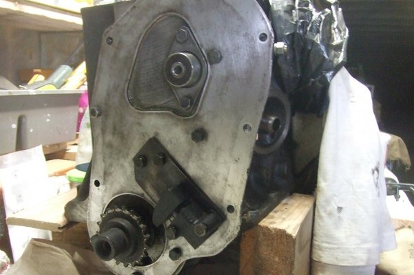
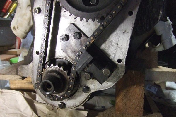
and then fixed to the side of the engine block. The tensioner and plate were put on temporarily to hold everything in place. I'll be taking it off again when I put on the timing chain and camshaft sprocket

DSCF6582.JPG
 
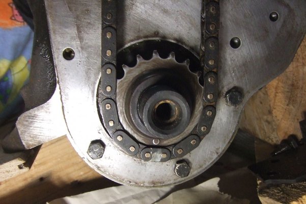
A big step forward today! When I dismantled the engine, I marked the chain with silver paint in line with the mark on the crankshaft sprocket. I also marked the chain in line with the mark on the camshaft sprocket.

DSCF6584.JPG
Looking at the end of the camshaft, you'll notice that the centre stands out from the shaft end by about 0,6mm. According to the manual, when the sprocket is put onto the shaft, the outer edge of the camshaft has to be flush with the inner ring on the sprocket (EDITED) See page 7 and page 8 for more information on fitting


DSCF6585.JPG
I put the sprocket in the oven for a bit to heat it and expand it. Perhaps the oven wasn't hot enough because it didn't really help. I put the chain over the sprocket, then fitted it to the camshaft. I didn't forget about the little metal key that slots into the groove on the camshaft end.
I had to smack it with a flat piece of wood to get it on all the way. With the heating, I had expected an easier fit.See page 7 and 8 for more fitting instructions

DSCF6586.JPG
Final step was to put on the chain tensioner

DSCF6588.JPG
 
Last edited:
Back
Top