


You are using an out of date browser. It may not display this or other websites correctly.
You should upgrade or use an alternative browser.
You should upgrade or use an alternative browser.
Restoration 1984 R4 GTL Rutger-peer
- Thread starter Rutger-peer
- Start date
")
Rutger-peer
The restoring Dutchman.
- Messages
- 260
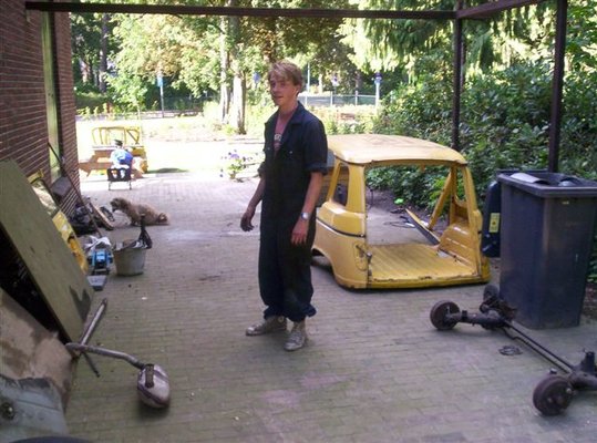
Haha, they look pretty okay right? No the sheep are real (wish they weren't because they break out all the time and make annoying noises ") ).
).
Bought a pot of C.I.P.-like primer. The shop assistant said he had the C.I.P. but only in small pots and the stuff I've got now was supposed to be the same kind of paint but cheaper. Well, we'll see wether it holds. Should be okay me thinks.
I'm now preparing all the suspension parts so they can be sprayed with primer!
Rutger-peer
The restoring Dutchman.
- Messages
- 260
Rutger please pay more attension to inside the chassis than the outside - all that glistens isnt gold or it will come back and bite you on the ass - here endeth todays lesson
Reg
Hey!
Was thinking about using Mike Sander grease inside the chassis so I guess that should do the trick
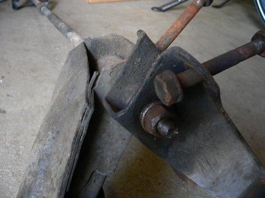
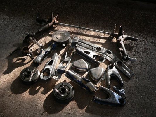
By the way, has anyone got any advice about how to take the torsion bar from the front suspension parts? The other side came off easily but this one is stuck. Put a screwdriver in the slot and a wrench on the nut already but doesn't help. See pictures Anyone ? EDIT: already been taken care of!
Also a picture of some cleaned parts
angel
Enthusiast
- Messages
- 2,615
- Location
- Athens, Greece
Spray the torsion bar splines with WD-40 or similar several times and let to soak for some time. Try to fix the lower suspension arm in a vice and rock the torsion bar from side to side several times. At some time you may feel it to move very slightly in the suspension arm, so try to pull it upwards. If it does not release, lay the assembly on the ground. Hit the suspension arm with a hammer (sharp blows) away from the torsion bar (like trying to push the arm forwards). The point to hit is immediately below the torsion bar splines, where the sheet metal parts are spot-welded together.
This one has worked for me several times, but the suspension arm was always fixed on the car. There is one more solution, to undo the lower arm pin nut (19mm) and try to push the bar out with the pin, either with the aid of a press, or with a hammer and drift. Note that the lower arm pin end does not stand too much hammering.
This one has worked for me several times, but the suspension arm was always fixed on the car. There is one more solution, to undo the lower arm pin nut (19mm) and try to push the bar out with the pin, either with the aid of a press, or with a hammer and drift. Note that the lower arm pin end does not stand too much hammering.
Rutger-peer
The restoring Dutchman.
- Messages
- 260
Hey Angel,
Thanks for the explanation.
But I already succeeded (as I mentioned in the above post). The problem was actually that pin-nut which wouldn't get loose. In the end I clamped the pin by pushing both sheetmetal parts another side and then using the impact wrench. It got loose in the end!
Thanks for the explanation.
But I already succeeded (as I mentioned in the above post
Rutger-peer
The restoring Dutchman.
- Messages
- 260
Hey guys,
Been cleaning parts today.
I am trying to get the suspension parts in the paint probably monday or tuesday. Next week I'll probably also bring the new chassis, as well as get some new parts.
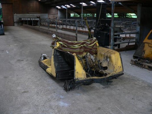
I got a question, which is: what is the sensible way to take apart the rear axle? Right now the two parts are still connected by the two tension bars. Are they on strain right now?
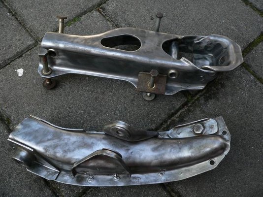
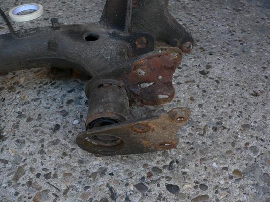
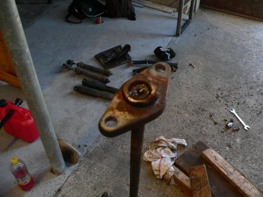
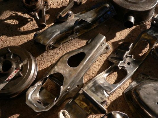
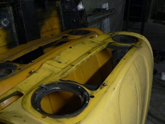
Picture one shows a wishbone with distorted holes, this was fixed by a former owner by putting in a ring with the correct holes. We will fix the wishbone with some welding, more on that later.
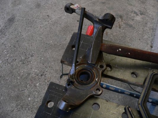
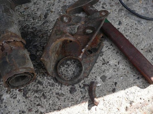
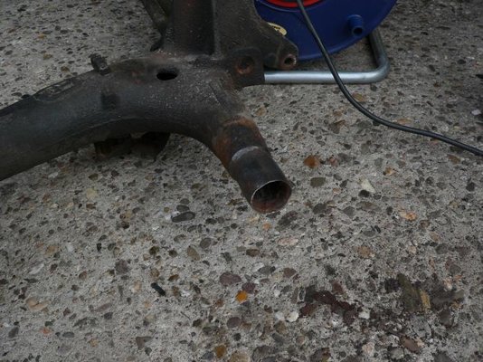
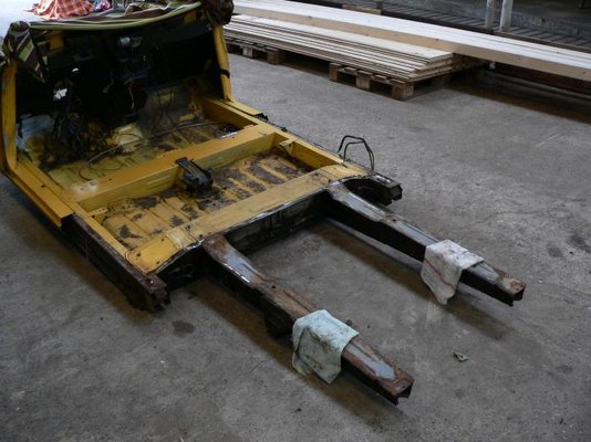
Also, one of the mounting brackets was really messed up so I had to cut it off the axle. The axle itself doesn't really look too nice too. I posted a picture of the outer end. Can somebody tell me if it's still usable? (pictures 4, 5 and 6).
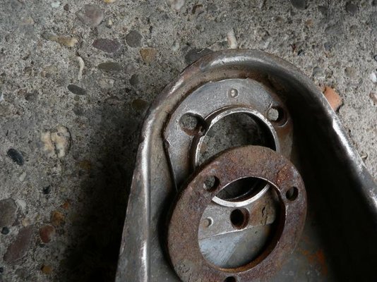
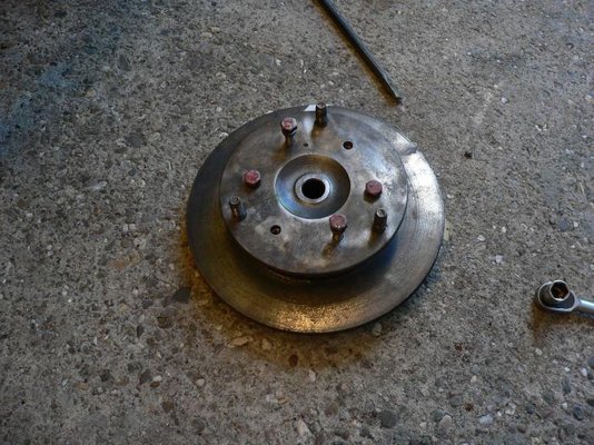
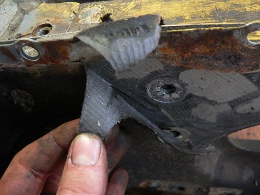
Another question is: what kind of sealant is there on the wheel bearings? (picture 2) I mean, is it meant to be there? I peeled it off because it wasn't in such a great shape and I will have to put in new wheel bearings anyway. Do these bearings have to be "special" R4-bearings or are they just also normal industrial ball bearings (though I noticed a little rubber ring on the big bearings)?
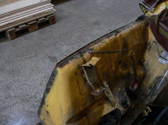
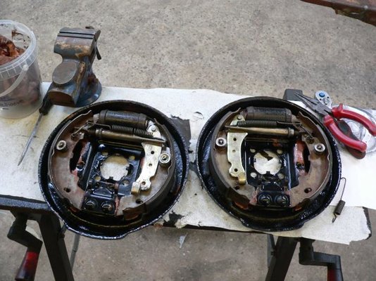
Still another question: should the parts that the break discs are attached to also be painted? (piture 3)
I also had a kind of a setback. I cleaned the parts up to bare metal very nice and shiny so the paint would attach well. But since the parts were left in the barn, they rusted over the surface in a few days due to humid air. That was pretty frustrating because I had to clean them all again with the steel brush. I now put them inside, where it's warm and dry. Hope they last well until we paint them.
Well, that was it for today.
Rutger.
Been cleaning parts today.
I am trying to get the suspension parts in the paint probably monday or tuesday. Next week I'll probably also bring the new chassis, as well as get some new parts.
I got a question, which is: what is the sensible way to take apart the rear axle? Right now the two parts are still connected by the two tension bars. Are they on strain right now?
Picture one shows a wishbone with distorted holes, this was fixed by a former owner by putting in a ring with the correct holes. We will fix the wishbone with some welding, more on that later.
Also, one of the mounting brackets was really messed up so I had to cut it off the axle. The axle itself doesn't really look too nice too. I posted a picture of the outer end. Can somebody tell me if it's still usable? (pictures 4, 5 and 6).
Another question is: what kind of sealant is there on the wheel bearings? (picture 2) I mean, is it meant to be there? I peeled it off because it wasn't in such a great shape and I will have to put in new wheel bearings anyway. Do these bearings have to be "special" R4-bearings or are they just also normal industrial ball bearings (though I noticed a little rubber ring on the big bearings)?
Still another question: should the parts that the break discs are attached to also be painted? (piture 3)
I also had a kind of a setback. I cleaned the parts up to bare metal very nice and shiny so the paint would attach well. But since the parts were left in the barn, they rusted over the surface in a few days due to humid air. That was pretty frustrating because I had to clean them all again with the steel brush. I now put them inside, where it's warm and dry. Hope they last well until we paint them.
Well, that was it for today.
Rutger.
pepper
Pepper The One and Only!
- Messages
- 2,251
If you take anything back to bare metal, then you "MUST" cover it with a protective coating as soon as possible, otherwise it will start to rust immediately!
When we shot blast our metal work we spray it in red oxide primer as soon as we've completed the blasting.
When we shot blast our metal work we spray it in red oxide primer as soon as we've completed the blasting.
Rutger-peer
The restoring Dutchman.
- Messages
- 260
If you take anything back to bare metal, then you "MUST" cover it with a protective coating as soon as possible, otherwise it will start to rust immediately!
When we shot blast our metal work we spray it in red oxide primer as soon as we've completed the blasting.
Hmm, makes sense indeed. But I have yet to have someone teach me how to use the painting facilities at the place I do the restoration, so I can't immediately paint it. Besides that, brushing pieces with a wire brush is quite time-consuming and the paintgun needs cleaning and so, so we figured it would be handy if we could paint all them parts at once.
But yeah, your method seems to be better. Well, anyway, in a few days things will be painted so...
Rutger-peer
The restoring Dutchman.
- Messages
- 260
Hi all,
It's been quite a while since I last posted something. For you guys who think I gave up or have been enjoying the sun in some sort of far off country: you are wrong!
Instead I've been sweating my ass off, grinding and brushing off rust, paint and all sorts of stuff that you normally only expect on things like a car-suspension....
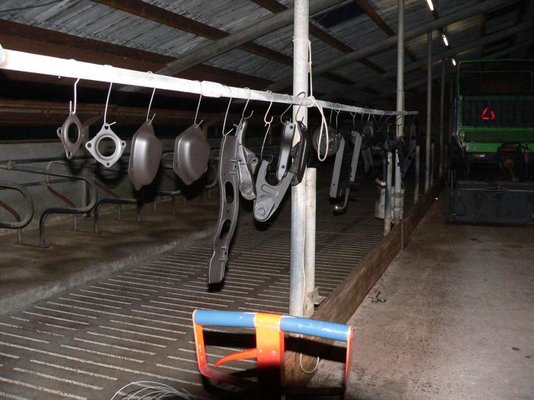
Oh, wait, it WAS a car-suspension that I have been cleaning actually. And yes, I finally finished the job. We applied the primer (which is black, oddly enough) and hopefully tomorrow I will apply the first coat of finish (the parts get two finishcoats). Also some non-suspension parts like the airfiltercap have been painted along with the suspension. It looks quite nice though the pictures I made of the painted parts were made at dusk so tomorrow I will be able to make some nice pictures which actually show anything at all.
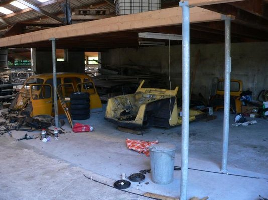
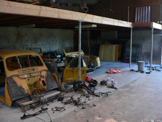
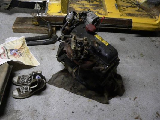
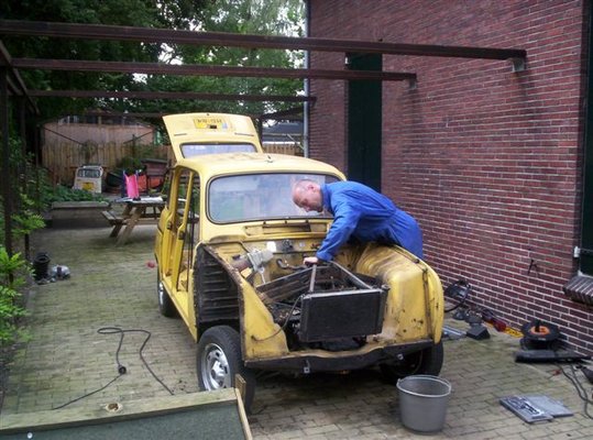
Next to that, I kind of got in a "chassis-crisis"... well, that crisis is over now since I've got me another chassis which is really good, except for the backbeams. Actually, during transport one of the beams got badly bent. I was able to bend it back into position a bit by foot so that says something about the beam. We will have to work on that. As for the rest, the chassis seems to be in really good condition and it hails from Spain. I have been busy a whole day with the owner disassembling the car around it and cutting off the body. I also bought the engine along with the chassis as well as the bonnet (which is bent as I saw just tonight, so I will have to get me another one still).
Also another nice feature is that the front suspension was still on the chassis. One of my wishbones was damaged so I can replace it. Moreover, the wishbones of this car are reinforced ones (just like on the F6) so my car gets extra strong wishbones! There was also a horn left on the chassis. Mine was badly rusted and this one was quite mint so I'll go with this one. I also took the inner wings along with it. That's also a big advantage since the passenger-side inner wing is really in a good condition and almost needs no welding at all (the edge is in very good condition all along it).
And the nicest thing of all is that i only cost me 150€, which translates to 125 GBP.
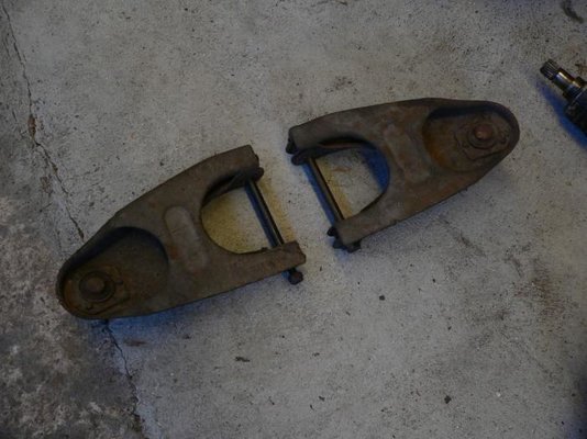
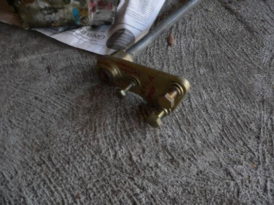
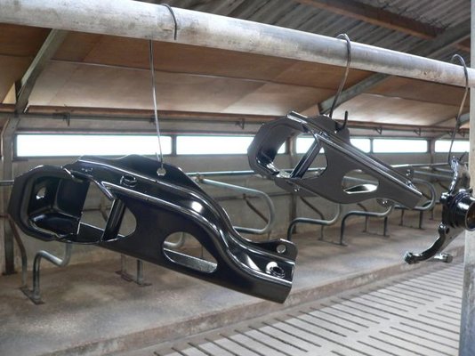
I found out that the torsionbars on this car are attached differently from my own chassis. Does anyone have an "explanation" or a "why" for that? I attached pictures of both ways (my own were the strange triangular type of attachments).
I attached some pictures of the disassembly and the chassis, engine, bonnet and the paintjob.
Greetings,
Rutger.
It's been quite a while since I last posted something. For you guys who think I gave up or have been enjoying the sun in some sort of far off country: you are wrong!
Instead I've been sweating my ass off, grinding and brushing off rust, paint and all sorts of stuff that you normally only expect on things like a car-suspension....
Oh, wait, it WAS a car-suspension that I have been cleaning actually. And yes, I finally finished the job. We applied the primer (which is black, oddly enough) and hopefully tomorrow I will apply the first coat of finish (the parts get two finishcoats). Also some non-suspension parts like the airfiltercap have been painted along with the suspension. It looks quite nice though the pictures I made of the painted parts were made at dusk so tomorrow I will be able to make some nice pictures which actually show anything at all
Next to that, I kind of got in a "chassis-crisis"... well, that crisis is over now since I've got me another chassis which is really good, except for the backbeams. Actually, during transport one of the beams got badly bent. I was able to bend it back into position a bit by foot so that says something about the beam. We will have to work on that. As for the rest, the chassis seems to be in really good condition and it hails from Spain. I have been busy a whole day with the owner disassembling the car around it and cutting off the body. I also bought the engine along with the chassis as well as the bonnet (which is bent as I saw just tonight, so I will have to get me another one still).
Also another nice feature is that the front suspension was still on the chassis. One of my wishbones was damaged so I can replace it. Moreover, the wishbones of this car are reinforced ones (just like on the F6) so my car gets extra strong wishbones!
There was also a horn left on the chassis. Mine was badly rusted and this one was quite mint so I'll go with this one. I also took the inner wings along with it. That's also a big advantage since the passenger-side inner wing is really in a good condition and almost needs no welding at all (the edge is in very good condition all along it). And the nicest thing of all is that i only cost me 150€, which translates to 125 GBP.
I found out that the torsionbars on this car are attached differently from my own chassis. Does anyone have an "explanation" or a "why" for that? I attached pictures of both ways (my own were the strange triangular type of attachments).
I attached some pictures of the disassembly and the chassis, engine, bonnet and the paintjob.
Greetings,
Rutger.
-
 P1070812.jpg57.4 KB · Views: 1,156
 -
 P1070815.jpg58.8 KB · Views: 1,165
 -
 P1070816.jpg56 KB · Views: 1,150
 -
 P1070829.jpg53.1 KB · Views: 1,166
 -
 P1070827.jpg59.4 KB · Views: 1,161
 -
 P1070828.jpg75.4 KB · Views: 1,175
 -
 P1070833.jpg55.7 KB · Views: 1,151
 -
 P1070834.jpg57.1 KB · Views: 1,165
 -
 P1070838.jpg75.7 KB · Views: 1,179
 -
 P1070841.jpg72.5 KB · Views: 1,154
Rutger-peer
The restoring Dutchman.
- Messages
- 260
And still some more pictures:
The painted parts
The spare engine
The two bonnets: notice how the lower part of the first bonnet (the light one) is bent forward, probably through bad hinges or so; somebody pushed through a bit and the bonnet bent.
Han, the man who sold me this and helped me disassemble the whole thing.
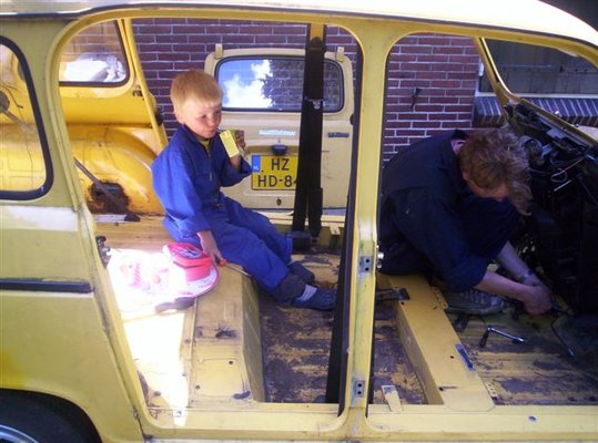
Me placing a springload along with our companion Ruben, the son of Han.
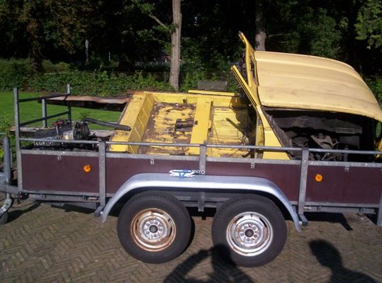
The stuff on the trailer, looked quite funny.
Me after a day of hard work, sweaty and greasy...
Also a few more questions:
- Are there different sorts of R4 bonnets (for the later models)? It looks to me as if the lighter bonnet is a bit more "curved" than the one that comes off my car.
- And does anyone know why there were 2 types of chassis? The one that comes from my car has flat backbeams, whereas this new one has curves in the upper surface, which requires welded-on pieces on the body so it won't bend through.
Rutger.
The painted parts
The spare engine
The two bonnets: notice how the lower part of the first bonnet (the light one) is bent forward, probably through bad hinges or so; somebody pushed through a bit and the bonnet bent.
Han, the man who sold me this and helped me disassemble the whole thing.
Me placing a springload along with our companion Ruben, the son of Han.
The stuff on the trailer, looked quite funny.
Me after a day of hard work, sweaty and greasy...
Also a few more questions:
- Are there different sorts of R4 bonnets (for the later models)? It looks to me as if the lighter bonnet is a bit more "curved" than the one that comes off my car.
- And does anyone know why there were 2 types of chassis? The one that comes from my car has flat backbeams, whereas this new one has curves in the upper surface, which requires welded-on pieces on the body so it won't bend through.
Rutger.
Rutger-peer
The restoring Dutchman.
- Messages
- 260
Okay, so where was I?
Last post I did was about getting the new chassis. Well, I've been quite busy in the meantime.
I took off the remaining part of the body and also took the inner wings off of that part with a blowtorch.
The chassis is now almost totally clean, all the sludge on the underneath has been cleared away with a steelbrush, a torch, plasterknifes ... I can tell everybody, it's a hell of a job but afterward you see every tiny hole and it's a hell of a nice look. The problem with the anti-stonechip underneath is that with a steelbrush you are only wiping it out, distributing it over the surface. But if you are persistent, it will eventually come off. I first removed the worst with a torch and a plasterknife and after that I removed the rest with a steelbrush on an axlegrinder. I attached some photos of that.
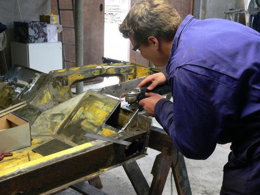
After that we started the welding. I can say that it worked very well and I think the result is astounding, thanks to a friend of mine who does the welding and who is really skilled. We welded all the parts with a full weld, not a spotweld each inch or something like that. Here and there we put in some plugwelds, where there used to be spotwelds.
Also I have been doing the spraying of the suspension parts. They are now in 2 coats of primer (rust preventing etc.) and one coat of finish, which in itself is suitable as a primer too and is also rustpreventive and conserving. I'm thinking of putting on yet another final coat for really good protection.
Tomorrow we will hopefully make some progress with the backbeams.
I attached some pictures. We also repaired another hole in the bottom, I haven't made a picture of the result yet so I will post that another time.
Descriptions about the pictures:
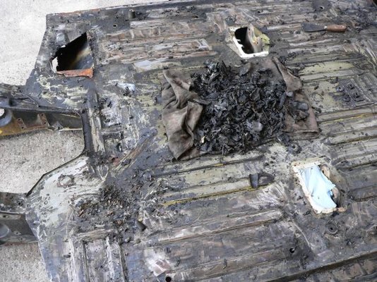
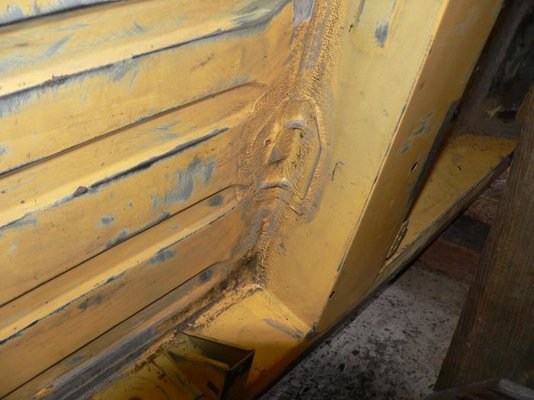
1 I still wonder what kind of stuff that is. The whole chassis was kinda covered with it and it seemed a very good protector. But I had to peel it off in order to do a proper paintjob.
2 Some finished parts
3 After the work with the torch. The worst has come off now (on the piece of cloth) and the rest will have to be done with the steelbrush.
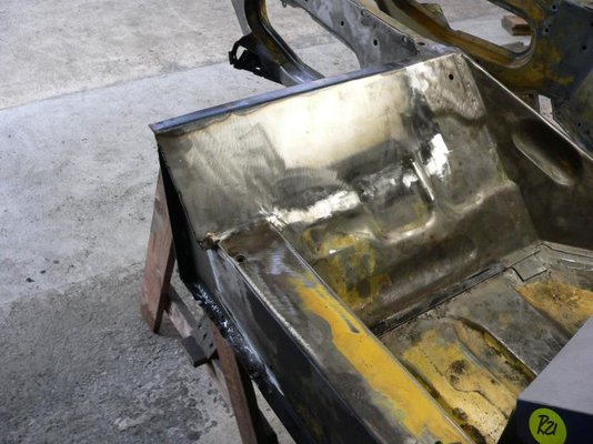
4 The sealing on this chassis is done very un-neatly. It seems like they've been blasting it in the seams with some sort of sealant pistol. Nevertheless: in that way the seams were protected very well. The downside is that the sealant is very abundant and also in places it doesn't have to be. I wanted to peel it off because we can't spray on top of it, since it is very hard to clean and second because when we wanted to roughen up the surface of the chassis-floor, we hit the sealant too with the wirebrush. This made it look nasty and made it prone to even catching more dirt. I almost peeled everything off now and I will apply new sealant.
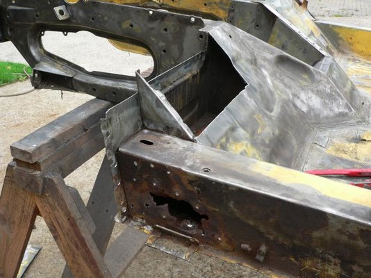
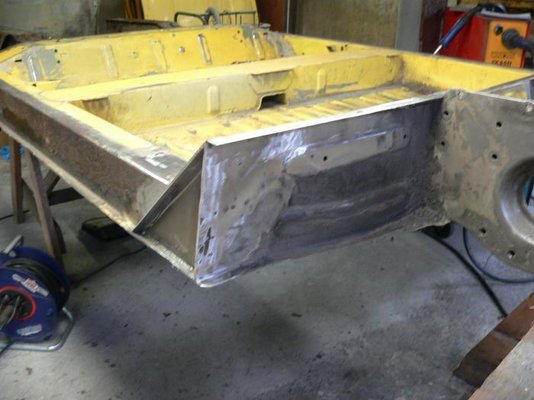
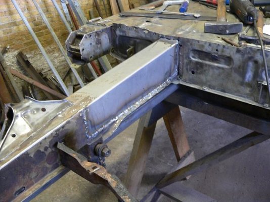
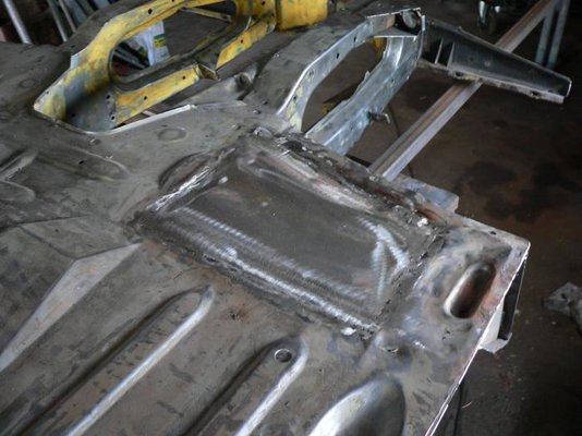
5 Big holes and we cut out the bad parts. We didn't wanna put in a new double skin but rather punt in one thicker piece of metal.
6 The result. A shame I didn't make more photographs of the between stages.
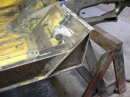
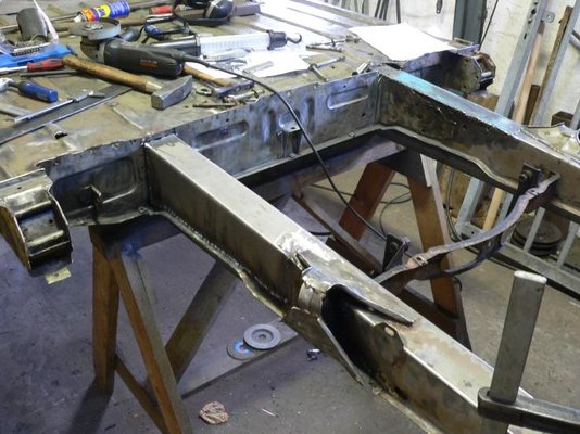
7 The result from the other side.
8 The other side, same kind of trouble, a bit less severe.
9 The result here
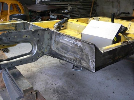
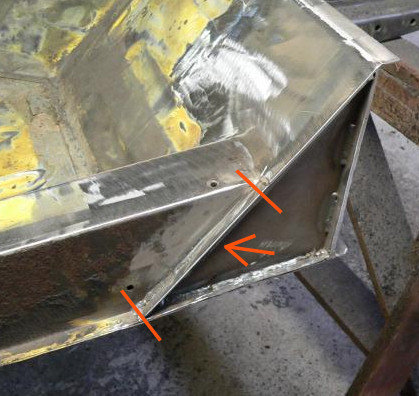
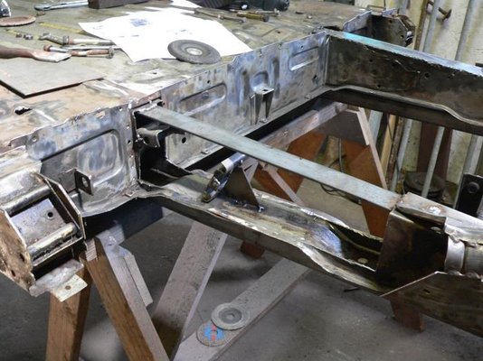
10 And from a different angle. By the way: it looks like there's not a whole weld on the front of that small triangulated plate. The fact is that the plate just as a bent edge, which is seamwelded to the frontplate of the chassis (you cant see that since the welder has neatly grinded all the welds flat). The2 pieces of seamweld you see in the picture are just for extra strength in the bend I guess.
Well, enjoy the photographs.
Regards, Rutger.
Last post I did was about getting the new chassis. Well, I've been quite busy in the meantime.
I took off the remaining part of the body and also took the inner wings off of that part with a blowtorch.
The chassis is now almost totally clean, all the sludge on the underneath has been cleared away with a steelbrush, a torch, plasterknifes ... I can tell everybody, it's a hell of a job but afterward you see every tiny hole and it's a hell of a nice look. The problem with the anti-stonechip underneath is that with a steelbrush you are only wiping it out, distributing it over the surface. But if you are persistent, it will eventually come off. I first removed the worst with a torch and a plasterknife and after that I removed the rest with a steelbrush on an axlegrinder. I attached some photos of that.
After that we started the welding. I can say that it worked very well and I think the result is astounding, thanks to a friend of mine who does the welding and who is really skilled. We welded all the parts with a full weld, not a spotweld each inch or something like that. Here and there we put in some plugwelds, where there used to be spotwelds.
Also I have been doing the spraying of the suspension parts. They are now in 2 coats of primer (rust preventing etc.) and one coat of finish, which in itself is suitable as a primer too and is also rustpreventive and conserving. I'm thinking of putting on yet another final coat for really good protection.
Tomorrow we will hopefully make some progress with the backbeams.
I attached some pictures. We also repaired another hole in the bottom, I haven't made a picture of the result yet so I will post that another time.
Descriptions about the pictures:
1 I still wonder what kind of stuff that is. The whole chassis was kinda covered with it and it seemed a very good protector. But I had to peel it off in order to do a proper paintjob.
2 Some finished parts
3 After the work with the torch. The worst has come off now (on the piece of cloth) and the rest will have to be done with the steelbrush.
4 The sealing on this chassis is done very un-neatly. It seems like they've been blasting it in the seams with some sort of sealant pistol. Nevertheless: in that way the seams were protected very well. The downside is that the sealant is very abundant and also in places it doesn't have to be. I wanted to peel it off because we can't spray on top of it, since it is very hard to clean and second because when we wanted to roughen up the surface of the chassis-floor, we hit the sealant too with the wirebrush. This made it look nasty and made it prone to even catching more dirt. I almost peeled everything off now and I will apply new sealant.
5 Big holes and we cut out the bad parts. We didn't wanna put in a new double skin but rather punt in one thicker piece of metal.
6 The result. A shame I didn't make more photographs of the between stages.
7 The result from the other side.
8 The other side, same kind of trouble, a bit less severe.
9 The result here
10 And from a different angle. By the way: it looks like there's not a whole weld on the front of that small triangulated plate. The fact is that the plate just as a bent edge, which is seamwelded to the frontplate of the chassis (you cant see that since the welder has neatly grinded all the welds flat). The2 pieces of seamweld you see in the picture are just for extra strength in the bend I guess.
Well, enjoy the photographs.
Regards, Rutger.
-
 P1080004.jpg50.8 KB · Views: 1,485
 -
 P1080010.jpg56.4 KB · Views: 1,520
 -
 P1080016.jpg96 KB · Views: 1,511
 -
 P1080046.jpg48.5 KB · Views: 1,488
 -
 P1080058.jpg63.1 KB · Views: 1,483
 -
 P1080069.jpg60.9 KB · Views: 1,482
 -
 P1080070.jpg53.2 KB · Views: 1,472
 -
 P1080072.jpg59.1 KB · Views: 1,479
 -
 P1080074.jpg45.5 KB · Views: 1,478
 -
 P1080076.jpg61.2 KB · Views: 1,495
Snoopy1974
Enthusiast
- Messages
- 412
 WAOUHH, great job ! ! !
Rutger-peer
The restoring Dutchman.
- Messages
- 260
Haha thanks, we were very proud of it ourselves too .
Rutger-peer
The restoring Dutchman.
- Messages
- 260
Thanks all for the compliments!
@ David: Well noticed! Someone on the Dutch R4 forum also told me it would be in the way. Basically, we forgot to take off that part of the edge and we ended up this way. We figured it would be no problem but it turns out it will indeed. We'll probably cut that part away. Thanks for notifying me!
@ David: Well noticed! Someone on the Dutch R4 forum also told me it would be in the way. Basically, we forgot to take off that part of the edge and we ended up this way. We figured it would be no problem but it turns out it will indeed. We'll probably cut that part away. Thanks for notifying me!
Rutger-peer
The restoring Dutchman.
- Messages
- 260
Hey all,
Since I've been a lazy host, all my apologies for that.
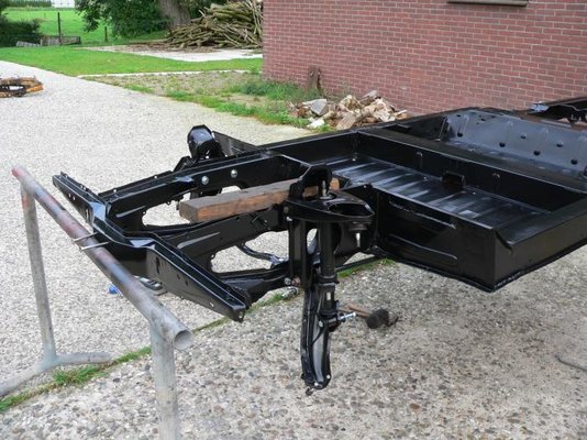
I've been making progress and my chassis is kind of rolling now, in a sense that it rolls but that's it. I still have to install the anti-roll bars, rear shock absorbers as well as some other things.
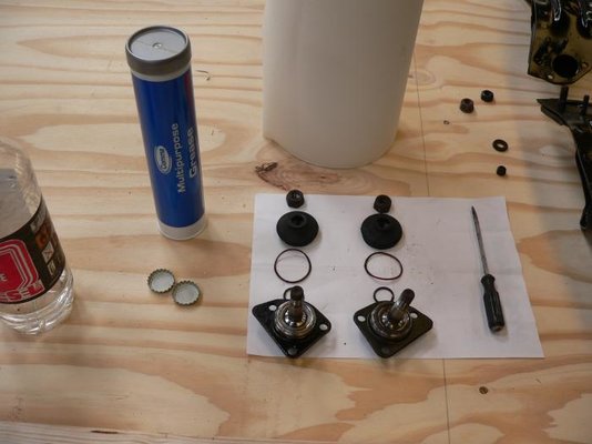
I'm trying not to post any long, tiring stories because the pictures speak for themselves. I will, however, say it was a difficult job getting the rear axle on since it didn't completely (on the millimeter) fit with the holes I drilled from the suspension jig I made. But after all I was able to get it back on. Also, the holes are really on the edge/lip of the backbeams. In order to mount the axle, I had to tear the lip of the backbeams a bit. The axle is also kinda tight around the backbeams, probably since we used some thicker sheetmetal. The result of that is that the rear torsion bars are a bit curved downwards, I hope that won't be such a big problem. I also hammered the new mountingbracket a little too far around the rear axle stump. I had to pull it back a little with a wheel dresser (is that the right word?), it wouldn't slide back but the rubber gave enough way to mount in to the chassis then. There is some sideward tension in the rubber now, so I hope it will settle a bit once I start driving the car. Otherwise the rubber could tear, we'll wait and see. The chassis is a little bit elevated on the backside now, but I think that will be fixed once I installed the rear shockabsorbers, can somebody confirm that to me? And has anyone got a picture of a rear shock absorber with the rubbers and rings still attached so I can see what's the proper way of putting it back on? I only got a pile of rubbers and metal rings now haha.
For the pictures, look below!
By the way, the pictures of the welding job when finished are made by the welder and he has still to send me those so I'll owe you those.
Greetings, Rutger.
Since I've been a lazy host, all my apologies for that.
I've been making progress and my chassis is kind of rolling now, in a sense that it rolls but that's it. I still have to install the anti-roll bars, rear shock absorbers as well as some other things.
I'm trying not to post any long, tiring stories because the pictures speak for themselves. I will, however, say it was a difficult job getting the rear axle on since it didn't completely (on the millimeter) fit with the holes I drilled from the suspension jig I made. But after all I was able to get it back on. Also, the holes are really on the edge/lip of the backbeams. In order to mount the axle, I had to tear the lip of the backbeams a bit. The axle is also kinda tight around the backbeams, probably since we used some thicker sheetmetal. The result of that is that the rear torsion bars are a bit curved downwards, I hope that won't be such a big problem. I also hammered the new mountingbracket a little too far around the rear axle stump. I had to pull it back a little with a wheel dresser (is that the right word?), it wouldn't slide back but the rubber gave enough way to mount in to the chassis then. There is some sideward tension in the rubber now, so I hope it will settle a bit once I start driving the car. Otherwise the rubber could tear, we'll wait and see. The chassis is a little bit elevated on the backside now, but I think that will be fixed once I installed the rear shockabsorbers, can somebody confirm that to me? And has anyone got a picture of a rear shock absorber with the rubbers and rings still attached so I can see what's the proper way of putting it back on? I only got a pile of rubbers and metal rings now haha.
For the pictures, look below!
By the way, the pictures of the welding job when finished are made by the welder and he has still to send me those so I'll owe you those.
Greetings, Rutger.
-
 P1080088.jpg65.6 KB · Views: 1,344
 -
 P1080090.jpg63.7 KB · Views: 1,245
 -
 P1080092.jpg66 KB · Views: 1,231
 -
 P1080095.jpg57.8 KB · Views: 1,229
 -
 P1080098.jpg53.4 KB · Views: 1,222
 -
 P1080106.jpg56.7 KB · Views: 1,240
 -
 P1080113.jpg39.3 KB · Views: 1,247
 -
 P1080123.jpg70.4 KB · Views: 1,241
 -
 P1080162.jpg92.5 KB · Views: 1,239
 -
 P1080167.jpg85.6 KB · Views: 1,237
Rutger-peer
The restoring Dutchman.
- Messages
- 260
And still some more pictures. I'd like to put some subscripts to the pictures but I was told to upload them through the forum, which will guarantee they will stay online, unlike when you upload them with imageshack or the like. I'll do that but it's a pity I can't make some desciptions that way.
Anyway, these are uploaded with imageshack:

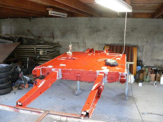
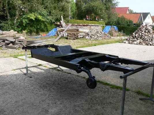
The chassis up and rolling. I guess it's elevated on the backside due to the missing shockabsorbers.

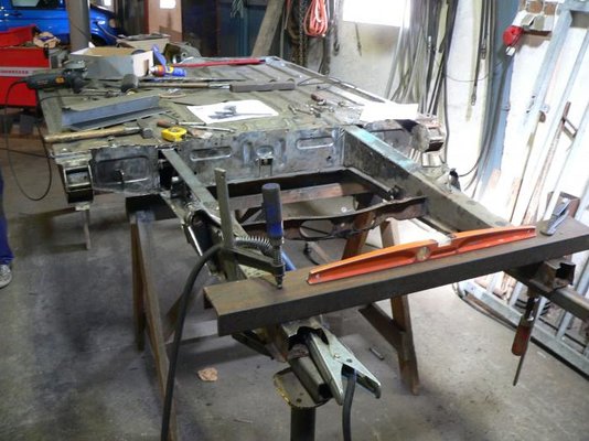
We used the palletfork of the tractor and a strap to get the torsionbars on tension. You can see how we did that in the picture. It worked very well. The fork was laid just on top of the chassis (no weight), to keep it from lifting when we would apply force and at the same time it served as something we could put the strap around.

A picture of the whole.
Anyway, these are uploaded with imageshack:
The chassis up and rolling. I guess it's elevated on the backside due to the missing shockabsorbers.
We used the palletfork of the tractor and a strap to get the torsionbars on tension. You can see how we did that in the picture. It worked very well. The fork was laid just on top of the chassis (no weight), to keep it from lifting when we would apply force and at the same time it served as something we could put the strap around.
A picture of the whole.