


JonathanT
Not normal for Norfolk
- Messages
- 1,335
- Location
- Wymondham Norfolk
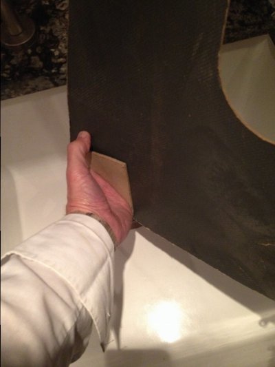
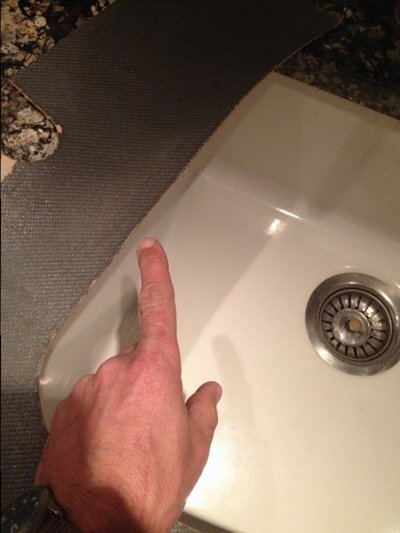
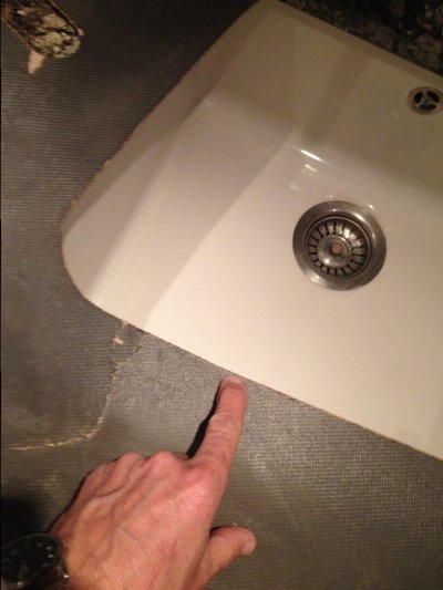
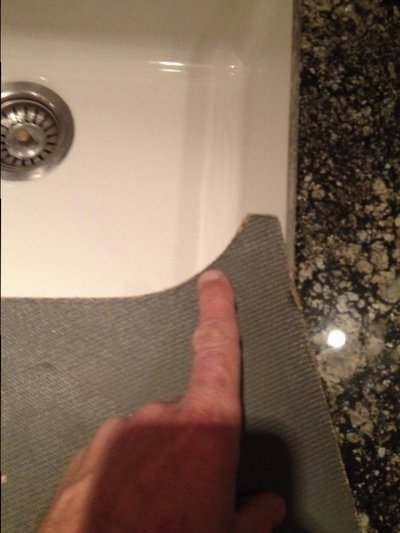
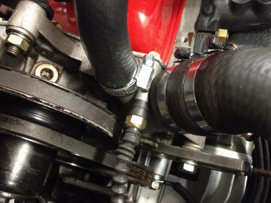
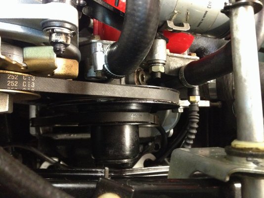
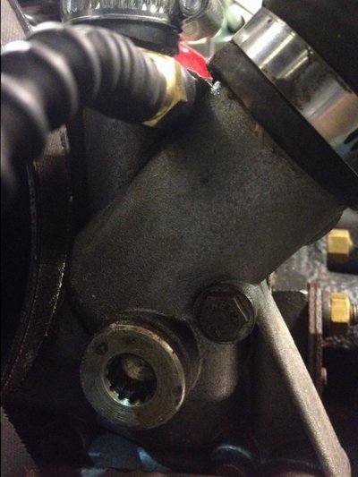
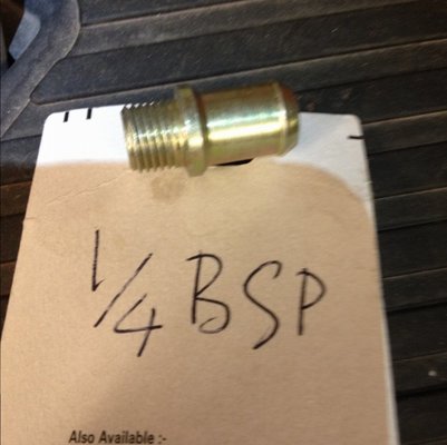
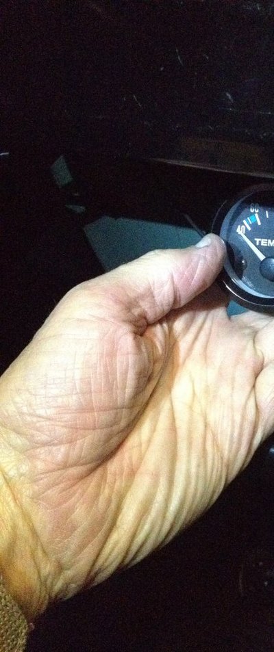
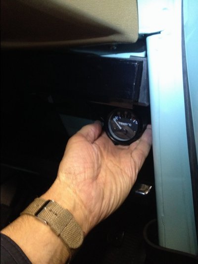
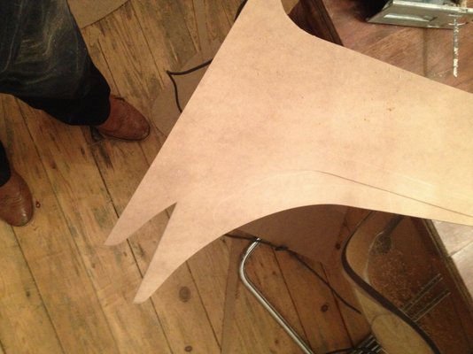
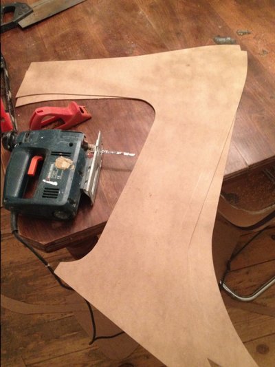
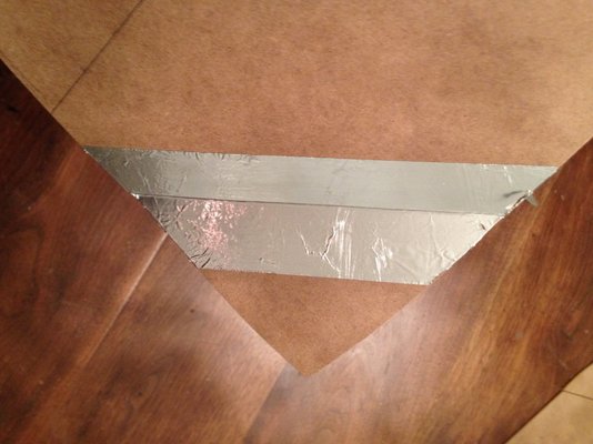
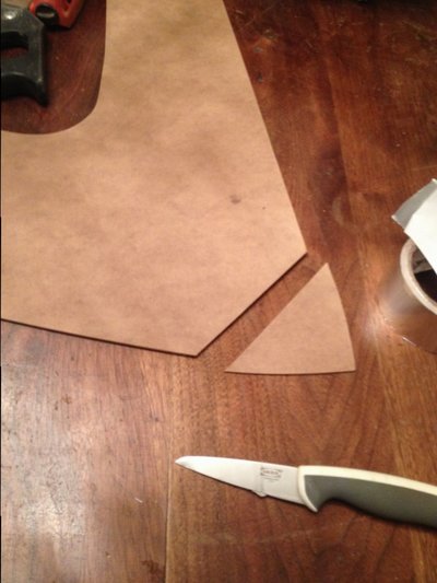
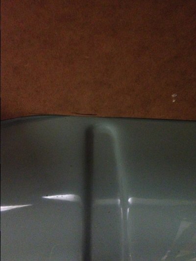
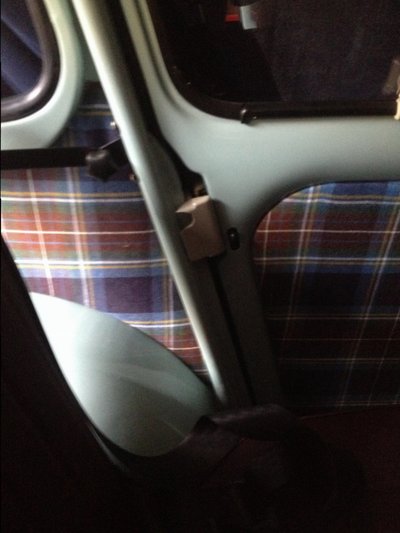
Ok here are some photos. You will see the sensor is pushed into a fixing bolt hole not a water jacket hole. The fit is snug and I held in place with a dab of threadlock. To make the installation more pleasing to the eye and a bit more professional I found up some bits of rubber from the bike repair tin and added those. I don't have a thread adaptor but I know they exist. The photo is of an extra outlet port that screws in. Two of these were supplied with the pump. It was one of these I was thinking of adapting till I discovered the neat bolt position in the photos. The thread of the additional /optional take off port is shown in photoJonathan, Could you please show a photo of exactly where on the water pump your adaptor and sensor is bolted? I am looking at exactly the same water temp gauge on eBay. Irritatingly I just know I have an original Smith water temp gauge somewhere in my workshop and for the life of me, I cannot find it. I've had it for forty years now!
(Later) Solved. I've found two plugs on the water pump and presume the one I need is the larger of the two and facing forwards. I can insert my little finger into the hex recess of the plug. After failing to find the Smiths temp gauge I have bought the same eBay one as you did. I'm curious as to the size of the special adaptor you have inherited (male & female threads). The sensor thread might be 1/8" NPT but there is no information about it in the eBay entry. I should be able to turn one up on my lathe.
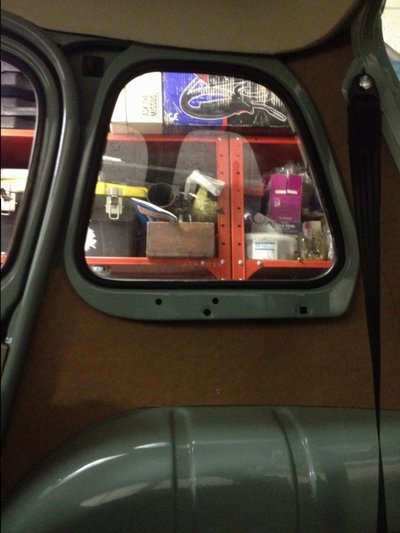
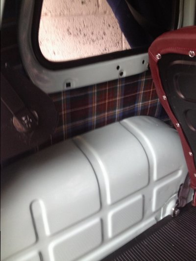
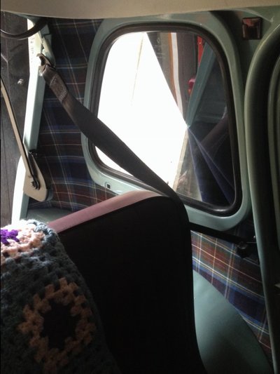
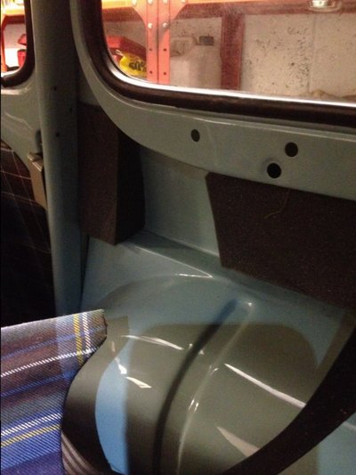
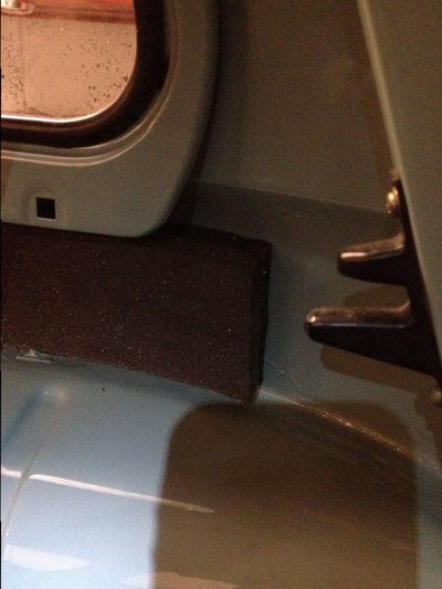
 And that blue tin was so very hard to get right with welding seat belt doubled up fixings etc
 Hoots Mon