Steering Column Modifications
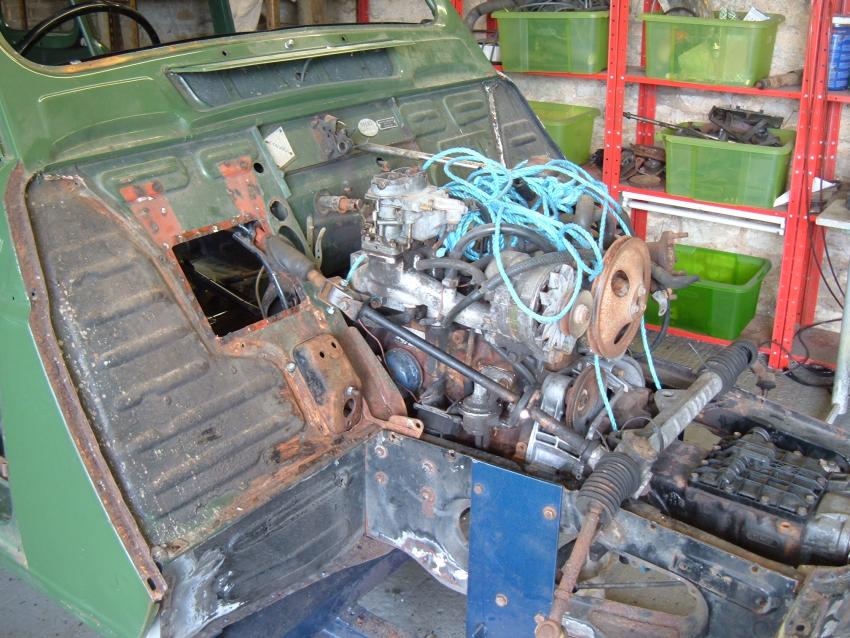
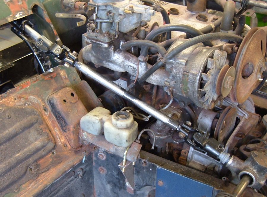
The Gordini engine used the same shape block as the GTL, but has the carburetor to the right of the engine rather than the left. This causes problems with the steering column.
None of the various steering columns fitted to the Renault 4 over the years will clear the carburetor manifold so I'll need to make a custom column.
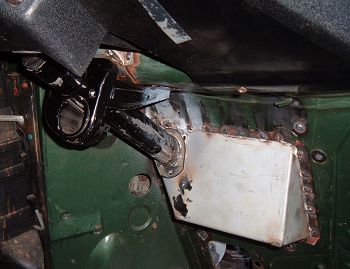
In the photo the battery tray has been removed (it would have been in the way) and the steering column moved about 30mm outboard.
Of course with the upper column mountings half way along the column, moving the shaft outboard made the steering wheel go inboard. A new upper column mounting would be required.
I should never have used the rare and irreplacable steering wheel for fitting up. My trial seat wasn't bolted down and fell backwards taking a chip out of the wheel. See the broken Quillery of Paris steering wheel page constructed to ask people for advice on repair.
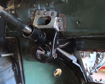
The upper mounting for the steering column had to be moved about 15mm outboard. The mounting photographs very badly because of the odd shapes and angles involved in it's construction. It's supposed to be that shape!
The design evolved through 2 cardboard templates, then was tried out in thin steel before the final 1.5mm thick part was fabricated to the most exacting of standards. I'm very pleased with the result but it was very tricky to figure out.
Based loosely on the original part it has extra reinforcement intended to stiffen the column mounting. The lower attachment will be reinforced by the battery tray supports.
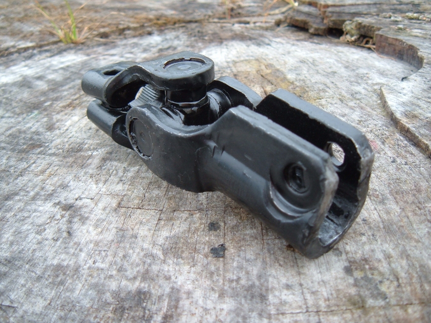
The original flexible joints were only intended to work at a small angle, so I had to use an alternative joint. I settled on one from a Ford Ka (also Fiesta Mk3). It's got a 36 spline 9/16 joint at one end and a 17mm hex at the other.
The hex is appealing as I've got the technology to cut a bar down to hex shape. My plan is to modify the upper column and steering rack to take the hex ends of the joint, and buy ready splined bar for the middle bit of the column.
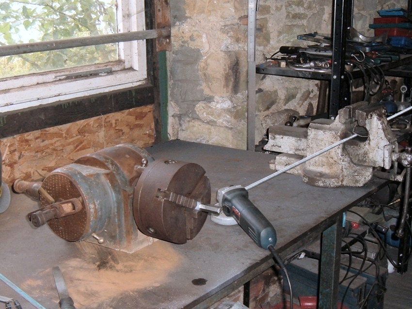
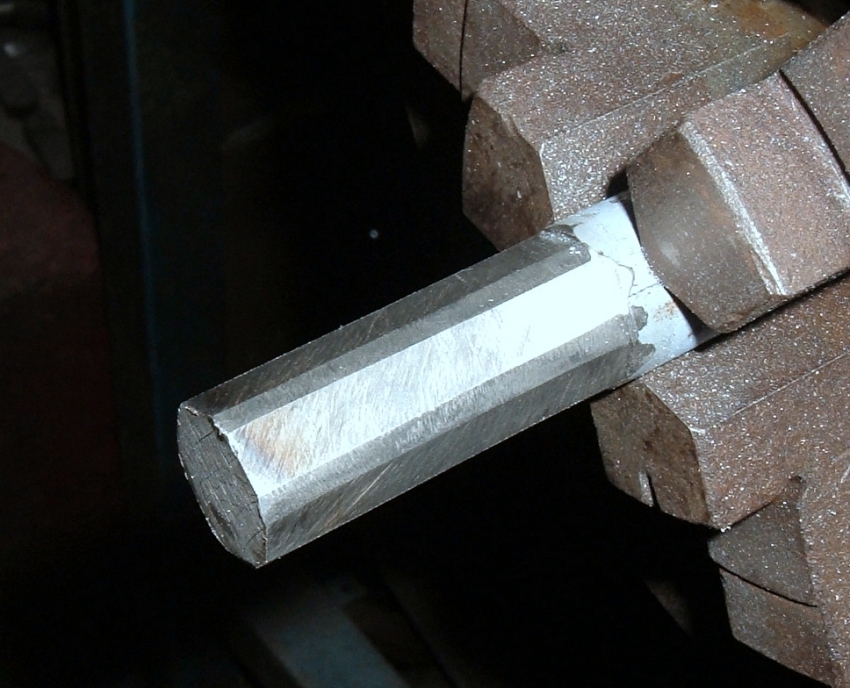
Here's the technology for making a hexagonal end on a round bar. It's an ancient universal dividing head built by Victoria Works in London in the late 1950's. The great thing about these dividing heads is you can stick bar in the chuck and rotate it round by a precise angle. They are unwanted these days so can be picked up for about £50, but this one was found rusted solid in the corner of a barn so was free.
There was no sign of the milling machine it came off, so I experimented using an an angle grinder. It was very tricky to keep the angle grinder at a steady angle. In the photo I've screwed some threaded bar into the handle slot and rested the other end on the vice. That controlled the angle of the grinder very well and made accurate cutting possible.
The hex shaft is described as 17mm hex, but that's not the whole story. It's 17mm hex cut into 18mm bar with the edges rounded off.
I did some testing with some spare bar to work out a good shape, and fettled this one a bit more by spraying primer onto the shaft, fitting the joint (using a hammer), and then filing it off a little where the joint had scraped. Pays to have a spare joint to use for this, but the Fiesta parts are cheap.
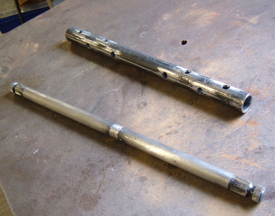
The splined shafts came from Car Builder Solutions. The shafts they sell are only splined at one end so I bought two. They were cut to length, the ends prepared into a "V" shape for welding, then welded together.
Just welding 2 pieces of shaft together is risky. Here I've gone for the belt and braces approach often used on steering columns. The tube with holes in beside the shaft is going to be a sleeve which will be plug welded to the shaft.
Here's the shaft after plug welding the sleeve on. I've not welded the ends of the shaft as that could cause stress concentrations especially if there is undercutting at the edge of the weld.
Besides it's not at all necessary - a couple of plug welds each end would hold two pieces of shaft together perfectly well and I've got 16 of them.
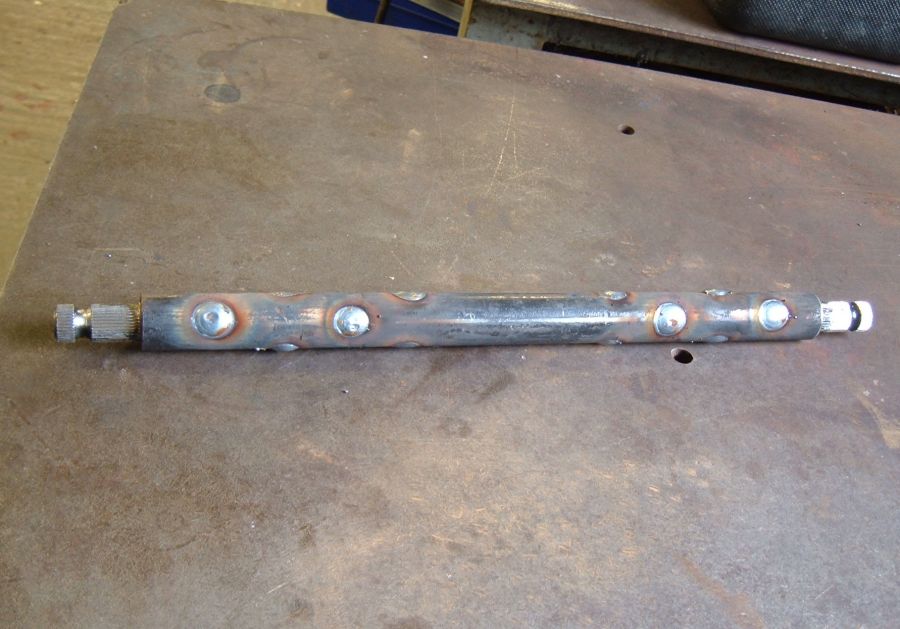
With the heads of the plug welds filed off for neatness I could finally assemble the finished steering column.
Sadly there is yet more work to do - the new joints are longer than the original Renault ones so I had to move the upper joint further back into the bulkhead. Hence the bulkhead shape will have to change a little.
I'm planning to fit the battery on the bulkhead using a similar arrangement to the original.
I've extended the battery tray inboards to provide clearance for the universal joint. . The hole for the steering column is very small in the photo. In the final version it would offer some clearance, but I wanted to check the position first so I would know which direction to enlarge the hole.
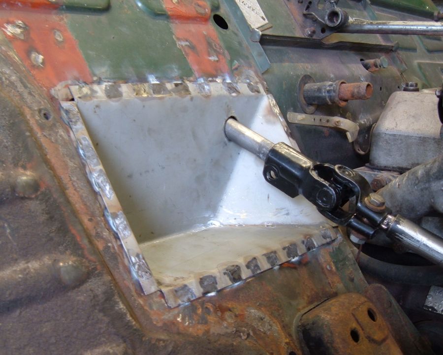
Modifications always have knock on effects. Having extended the battery tray for clearance I needed a new mounting for the steering column. It's a 3mm thick sheet of metal welded to the end of the column with a single bolt fastening it to the battery tray.
The mounting will also act as a seal as there isn't enough space for the standard seal on the other side of the bulkhead. Most likely I'll use sealant to complete the seal.
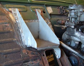
Finally the new battery tray could be welded in place. It's about an inch narrower than the standard battery tray but about an inch longer. It will take the standard GTL battery, but will be fitted with an Asia type battery of a similar size (but without the lip at the bottom).
There's a dog leg support on the inboard side of the battery tray. That's more to do with stiffening up the brake mounting than the battery tray. Still some tidying up to do - there are a couple of extra reinforcements at the top of the battery tray supports found on the standard car that will be fitted to this for the sake of "originality", and some supports for the battery clamp, but that's it for the interesting stuff.
If something is worth doing it's worth doing twice!
The page has covered my final attempt at the steering column. The first attempt involved using the type of steering joint originally used on Renault 4s. The "bearings" in the Renault joint were rubber bushes. After assembling everything I wasn't happy with them. There was too much torsional movement in the steering shaft due to the rubber busing in the joints and the steering was a little heavy.
Next> Air intake modifications, or back to the Gordini Project


Reassembly
Engine
Paint
Body welding
Engine bay
Chassis welding
Outer rear suspension mounting